4D seismic fundamentals
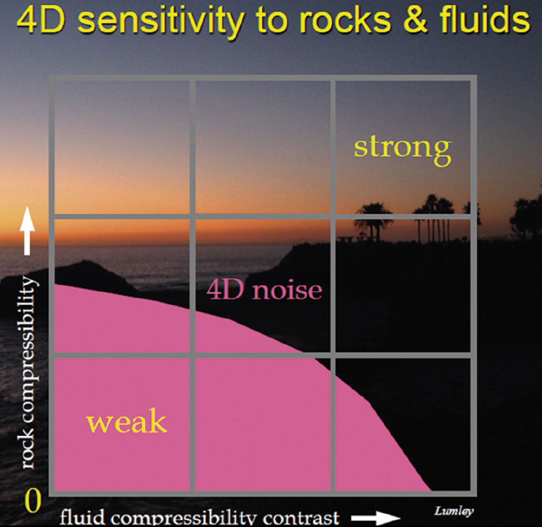
4D seismic involves repeating 3D seismic surveys in timelapse mode to image changes in subsurface fluid flow over time, whether due to injection or depletion in a hydrocarbon reservoir, injection and storage of CO2 for sequestration projects, or other subsurface processes such as groundwater flow or environmental contaminant remediation. To first order, seismic waves measure the compressibility of the subsurface porous rock-fluid system. Thus, in order to create a 4D seismic signal, the fluid-saturated rock compressibility must change over time. In general, the more compressible the rock matrix (eg. unconsolidated sand) and the larger the compressibility contrast between the two or more fluids replacing each other (eg. water and gas), the larger the 4D seismic signal. Conversely, stiff rocks and/or similarly compressible fluids produce a weak 4D signal (Figure 1).
As with the measurement of any physical phenomenon, the ability to detect a 4D signal in field data depends both on the magnitude of the signal and on the noise level in the data. With 4D seismic data, the largest source of noise tends to be what we call “non-repeatable” noise, which results from the fact that we cannot perfectly repeat the seismic imaging experiment and its environmental conditions from one survey to the next. A common way to measure non-repeatable noise is to difference two data sets/images, and compute the energy of the difference data/image compared to the energy of each individual data/image. This measure is often called the “NRMS” value. In a perfectly repeatable world NRMS=0, if the two data sets consisted of random uncorrelated noise NRMS=1.4, and if the data sets were identical but polarity-reversed NRMS=2. With todays 4D best acquisition and processing techniques, NMRS values of about 0.4-0.6 are considered good, and NRMS values less than 0.2 are considered excellent.
Future requirements for 4D seismic technology
Future improvements in 4D seismic monitoring will require two important objectives: 1) improving 4D signal-to-noise (S/N) levels in order to detect very weak 4D signals, and 2) improving processing flows and algorithms to correctly image fluid-flow anomalies when the 4D signal is so strong that it generates highly complex wavefields that are not properly handled by current methods. To improve 4D S/N, for example to reduce NRMS values to significantly less than 0.2, there will need to be new developments in seismic acquisition technology specifically for 4D objectives. These developments will include improvements in accurate positioning of seismic sources and sensors (eg. multi-boat acquisition, wide-tow arrays of both sources and receivers, DGPS sensors on gun arrays, accurate measurement of receiver locations, permanent arrays…), and better measurements of near-surface variations in the water or soil layer (eg. use of satellite-based tide and wave-height data, acoustic fish to measure water velocity-depth profiles, sensors to accurately measure groundwater fluctuations and changes in the near-surface soil properties…), coupled with processing algorithms that accurately make use of such new measurement data.
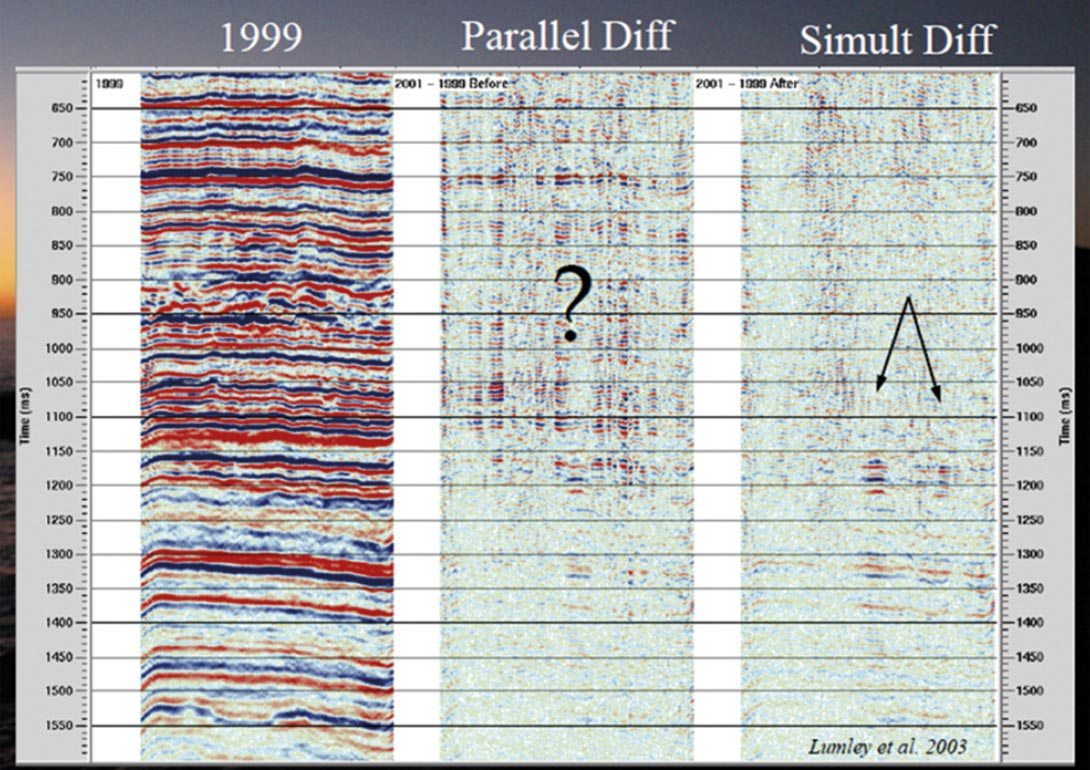
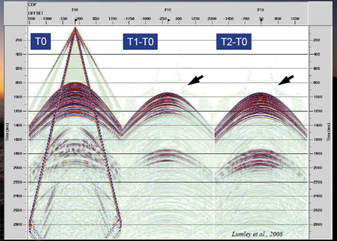
There is a need to develop improved seismic processing tools and imaging algorithms specifically for 4D objectives. One area that has shown encouraging results is to treat the imaging of a 4D seismic data set as a global optimization problem by addressing all of the 3D data sets simultaneously, constrained by the fact that some parts of the subsurface are changing whereas other parts are not, versus the current best practice of processing a 4D data set as a series of 3D individual data sets using the same or similar processing flows and parameters, analogous to local optimization (Figure 2). In the case of strong 4D reservoir changes (injection of gas, steam, CO2…), new algorithms are needed to accurately reconstruct the complex wavefield (multipathing, interbed multiples, conversions…) generated in such situations (Figure 3), including 4D prestack depth migration velocity analysis, 4D reverse-time migration algorithms or equivalent, and 4D elastic imaging to accommodate both P-waves and S-waves in such data.
Monitoring oil and gas production
4D seismic has been successfully applied in a commercial sense for more than a decade now, with monitoring applications including primary oil and gas depletion, injection of water, gas, steam and CO2, pressure maintenance, fault transmissibility, compartmentalization, geomechanical compaction and dilation, among others. For example, some large heavy oil projects spend millions of dollars per day to generate steam for injection, and 4D seismic is used as a routine part of the production plan to monitor the injected steam and adjust the injector/producer well profiles to maximize oil recovery. As an example of applications to more conventional oil and gas production, StatoilHydro have publicly stated that they estimate the net value directly attributed to applying 4D seismic is over $1 Billion for the giant Gullfaks oilfield, and over $4 Billion for their monitored North Sea assets.
New technology for 4D seismic oil and gas monitoring will be required to better monitor gas depletion fields (small 4D signal), quantify changes in reservoir properties from seismic rather than simply making qualitative images (ie. estimate physical values of pressure, saturation…), and assist in closing-the-loop workflows to update reservoir geology and flow models to better match and predict reservoir performance.
Monitoring CO2 sequestration
We are about to face a huge increase in the need for geophysical characterization and monitoring of subsurface reservoirs and aquifers for CO2 sequestration projects. Global energy demands are rising significantly, driven by world population increase and the growth of third world economies. At the current rate of development of sizable alternate energy sources, it is predicted that the world will have to rely even more heavily on carbon-based fuels to meet the impending energy demand. With global oil supply near its peak or perhaps already in decline, this will place an increased emphasis on obtaining carbon-based fuel sources from LNG, coal, and unconventional hydrocarbon resources like tight gas, coalbed methane and heavy-oil tar sands. All of these carbonbased energy sources, especially coal-fired power plants, LNG, and tar sand operations, will create a growing excess supply of CO2. Whether man-made CO2 emissions are a significant cause of global climate change, or highly correlated with global temperature rise, there will be increasing pressure from world governments to reduce the amount of CO2 emissions to the atmosphere, via policy change (eg. Kyoto, Copenhagen…) or financial measures (eg. carbon tax, cap and trade...). Capturing industrial CO2 at its various sources and injecting it into deep geologic formations for longterm storage (sequestration) appears to be one of the most practical potential methods to achieve significant reductions in atmospheric CO2 emissions.
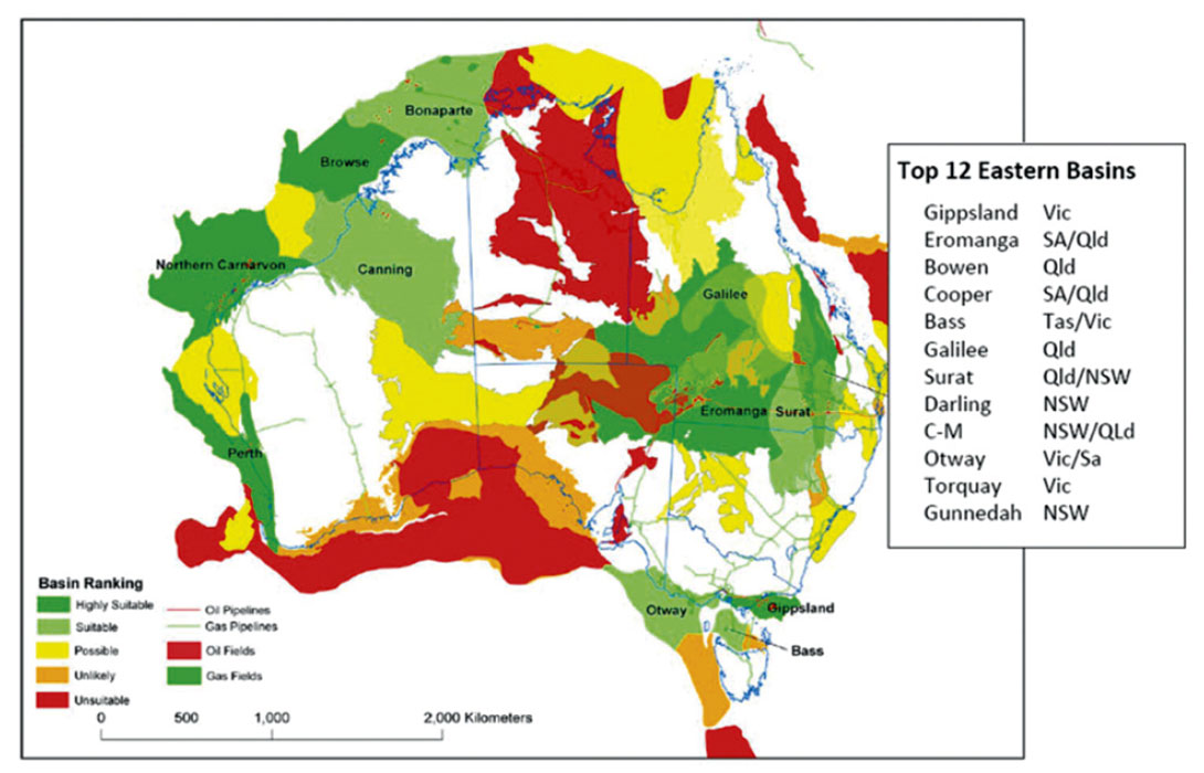
The basic CO2 sequestration approach will be to capture it at a source (eg. coal-fired power plant, LNG facility, or tar sands operation) and inject it into a deep geologic formation located nearby. Subsurface storage targets include depleted hydrocarbon reservoirs, and saline aquifers. A massive undertaking has already started to locate and rank subsurface candidates for CO2 sequestration among the world’s sedimentary basins, and future work will require detailed geologic and geophysical site characterization of these reservoirs/aquifers in terms of better defining storage capacity (volume, porosity…), injectivity (permeability, geologic structure…), and sealing efficiency (CO2 buoyancy and flow gradients, structural traps, fault transmissibility, geochemistry…). Australia has recently become the first nation in the world to open up offshore exploration leases specifically for the purpose of locating possible subsurface CO2 storage sites in preparation for a future market in CO2 sequestration (Figure 4).
In addition to site characterization, there will be a huge demand for geophysical monitoring and verification technology for CO2 sequestration. As operators inject CO2 into the subsurface, there will be a need to image and monitor the CO2 to make sure that it is being injected at the correct depth and location, that it fills the storage reservoir efficiently as predicted, that it does not flow toward risky areas such as large faults with uncertain fault seal properties, and that it remains sealed in the reservoir over time and does not escape to the surface or interfere with other subsurface users (oil, gas, minerals, groundwater…). Furthermore, in order for an operator to effectively transfer CO2 sequestration project liability to a government or other agency, regulators will likely require that the operator build a 3D digital subsurface model that adequately explains and predicts the CO2 injection and monitoring data for a significant period of time (eg. 25-50 years), and closes the loop in terms of matching the reservoir geology, flow simulations and geophysical images of CO2 distribution. This will require advances in CO2 sequestration geophysics including: core measurements of the fluid-flow and geochemical effects of CO2 on rock properties, computational simulations and algorithms to better predict and image the effects of CO2 injection in the subsurface, and inversion of geophysical data to make 4D quantitative estimates of the amount of CO2 in place. Due to the complexity of CO2 geophysics, achieving these goals will require combing the powerful monitoring technique of 4D seismic with other geophysical methods such as passive microseismic, electromagnetics (EM), gravity and inSAR satellite imaging.

Related Reading


Join the Conversation
Interested in starting, or contributing to a conversation about an article or issue of the RECORDER? Join our CSEG LinkedIn Group.
Share This Article