Introduction
Resolution! A constant plea from interpreters, drilling engineers, and other end users of seismic technology is for better resolution. Consequently, this is a key attribute of interest when designing seismic surveys. The requirements specified by customers are usually given in terms of temporal resolution. So survey design strategies often focus on things like what temporal frequencies can be put into the earth – as, for instance, what frequencies can be swept by a vibrator without inducing excessive distortion.
By contrast, specific attention to the spatial resolution issue is often still immature. Methods used in survey design studies for estimating spatial resolution are often based on rather simple rules of thumb such as “λ/4”.
But whatever the case, key to both temporal and spatial resolution is the issue of spatial sampling. So the purpose of this paper is to examine this interplay. We hope to show that the topics of temporal resolution and spatial resolution are very much intertwined, that resolution values are able to be quantified better than is often done in survey planning, and that spatial sampling is a crucial parameter in all these regards.
In order to keep this article to a prescribed length, we will limit our focus to discussions of signal (not noise) in onshore, vibrator surveys. To get started with this, we will look at some ways to quantify resolution.
Quantifying resolution – analytic spatial wavelets
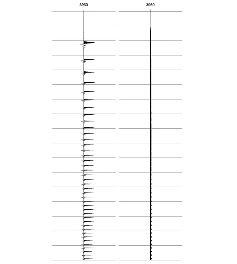
In a well-regarded empirical study, Kallweit and Wood (1982) used the Rayleigh criterion described in Figure 1 to quantify temporal resolution. They observed that in the noise-free, zero-phase case when at least two octaves of white bandwidth are present, the limit of temporal resolution can be expressed as 1/(1.4 x FMAX ).
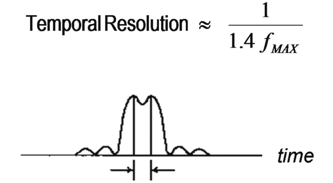
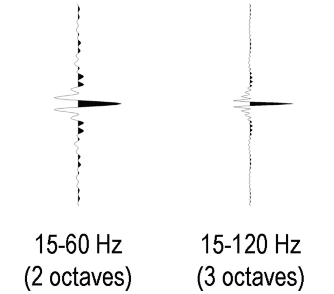
Note, some readers might be more familiar with other measures of temporal resolution that rely on, say, the peak frequency – as in the case of Ricker wavelets. But the boxcar spectral shape considered by Kallweit and Wood calls for FMAX in the quantification of resolution. So in this regard, two wavelets are shown in Figure 2. They have the same FMIN values – namely, 15 Hz. But by virtue of their different FMAX values, 120 Hz and 60 Hz, the temporal resolutions are calculated to be 6 ms and 12 ms respectively.
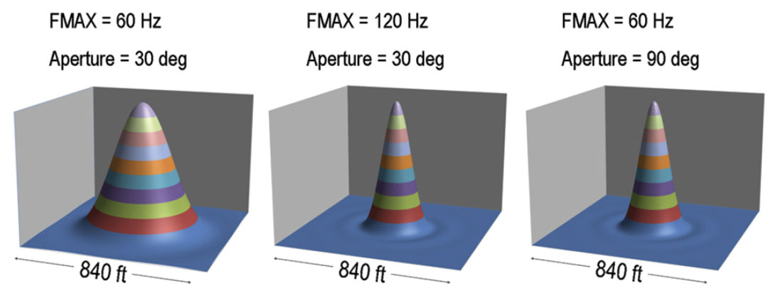
Conveniently, in addition to knowing the FMAX values, if we also know the velocity of the medium and the maximum dip comprising the migration operator, we can additionally use the Rayleigh criterion to quantify the spatial resolution. This is made possible through use of the spatial wavelet concept as discussed by Berkhout (1984). So for a velocity value of 15,748 ft/s and a migration aperture of 30 degrees, Figure 3 shows the spatial wavelets that correspond to the temporal wavelets in the previous figure. Their lateral resolution values are 155 ft and 303 ft respectively. So we see that holding all other factors constant, higher temporal FMAX values not only lead to better temporal resolution, they lead to better spatial resolution too.
Also shown in Figure 3 is the spatial wavelet for the case where FMAX is 60 Hz and the aperture is 90 degrees. This yields the same lateral resolution as the 120 Hz, 30 degree case. So if it is known, for instance, that access in a survey area will be restricted, thereby limiting the migration aperture, then we can compensate for it if we can boost the temporal frequency content.
So does this really mean that we can use these spatial wavelets to predict accurately what the final resolution will be? Well, not necessarily. Berkhout’s formulation gives a natural limit derived from analytic integration of continuous functions. But in seismic surveys, we deal with the numerical integration of sampled data. Dealing with the aliasing issues that arise from temporal and spatial sampling can impose further limits on the resolution. To demonstrate this, we will consider a case from West Texas.
Example from West Texas
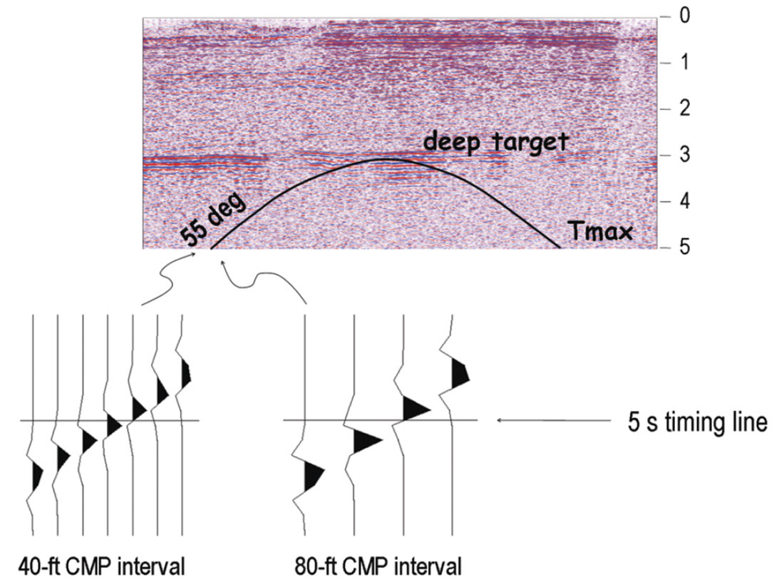
Figure 4 shows a brute stack from the Reeves and Loving County area of West Texas. A key target lies at a 2-way time of 3 seconds. A new 3D survey was being planned. Legacy programs had used a CMP bin spacing of 110 ft. It was believed that new-generation seismic efforts should use closer spacing. The two chief geometries being considered could provide CMP bins whose dimensions were 80 ft x 80 ft and 40 ft x 40 ft respectively. The question was which design should be used – or perhaps should other completely different designs be considered instead.
Now to compute the analytic spatial wavelet and thereby get an estimate of what would be the best possible lateral resolution available at the zone of interest, three inputs were needed. They were velocity, FMAX, and aperture. The velocity was known from well logs and previous seismic surveys. The equation of the analytic spatial wavelet called for a constant velocity value only, so the interval velocity at the target level was used.
Analyses of the legacy seismic surveys showed that frequencies up to 70 Hz could sometimes be preserved at the target level. However, subsequent field tests with a single-sensor system indicated that frequencies as high as 100 Hz might be able to be preserved in future programs. So 100 Hz is the value that was assigned to FMAX for the purposes of predicting the new spatial resolution. And finally, again from analysis of previous seismic surveys, it was felt that 5 seconds would be a sufficient limit for TMAX. So the trajectory of a zero-offset diffraction curve centered at the deep target was computed. It is plotted on the stack section in Figure 4. Those calculations showed that the 5- second temporal aperture limited the zero-offset dip aperture to 55 degrees.
So using those inputs, the analytic spatial wavelet was computed. Imposing the Rayleigh criterion then indicated that the limit of spatial resolution for the deep target would be approximately 102 ft. The next question was if candidate survey designs could generate seismic resolution that would actually approach that limit.
Some quick calculations showed that with a CMP interval of 80 ft, the 55-degree tail of the zero-offset diffraction surface would alias at 55 Hz. With a CMP interval of 40 ft, the aliasing would not occur until 110 Hz. Therefore it seemed that the 80-ft design would not fully exploit the 100-Hz FMAX opportunity whereas the 40-ft design might. In order to do a more thorough analysis, it was necessary to take into account non-zero offsets too, and it was important to see exactly what state-of-the-art migration codes would do. To do this, pre-stack Kirchhoff migration was executed in controlled numerical experiments. But before we discuss those experiments, we first need to describe the antialiasing operation that is implemented within such migration algorithms.
Anti-alias filtering within migration routines
Consider a point diffractor model that has a constant offset geometry consisting of a single source and a single receiver.
Figure 5 shows snapshots of several consecutive shotpoints. The rays that go from the source to the point diffractor, and then from there to the receiver are shown in black.
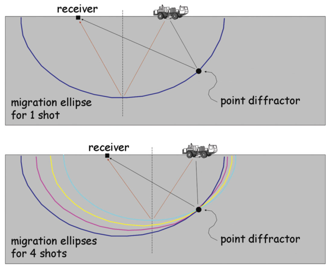
At the time of data acquisition, we do not know where the diffractor is, so we initially assume it is at the midpoint. Those assumed rays are shown in dark red. Then in the migration process we smear the data along a constant time surface. In these cartoons we assumed the velocity of the earth to be constant. That means each time surface is an ellipsoid with the source and receiver at the two foci. (Note, this is not the same earth model as in the West Texas case.)
We see that the ellipses add up at the location of the point diffractor. We hope that this constructive reinforcement is so powerful that all of the other spurious parts of the wavefronts that fall in other CMP bins look negligible by comparison – thereby producing a migration section that essentially shows only the point diffractor itself.
However, depending on the CMP bin dimensions, we usually need to help the process of suppressing the spurious wavefronts. To see that, let’s look at the CMP bin denoted in Figure 6. The point diffractor does not lie inside that bin, so our image should be nil there. However, we see from the demonstration that 5 wavefronts are swung into that bin by the migration process. The wavelets corresponding to those wavefronts are shown on the left-most cartoon trace. They are color-coded as per the cartoon wavefronts. The resultant seismic trace for that output bin is the sum of those 5 arrivals. That resultant trace is labeled “sum” in the figure. We see that when peaks line up with troughs, there is annihilation of the amplitudes in the summed trace. But up in the top part of the trace, the wavelets are severely aliased. So there is no destructive interference. This lets amplitudes leak through – thereby generating artifacts.
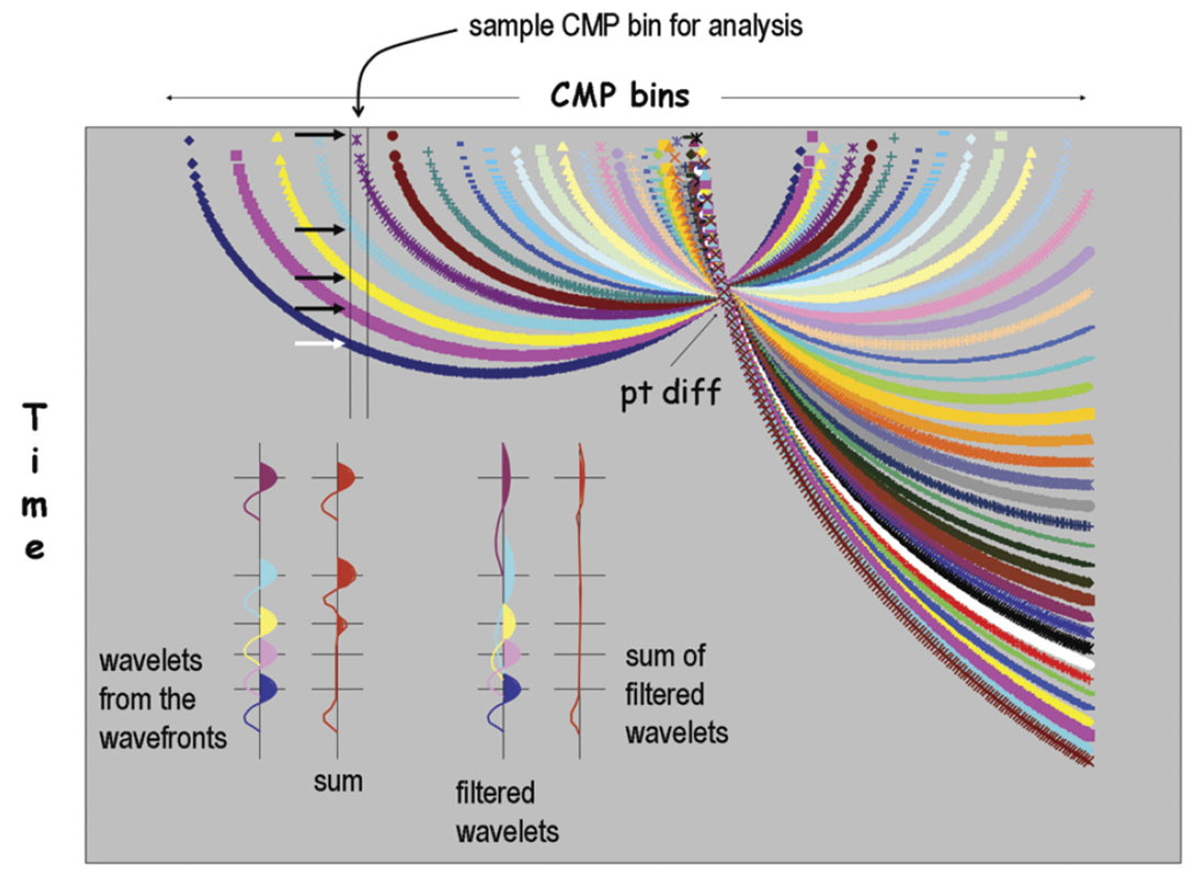
So what we do as part of the migration process is filter out the high frequencies that belong to the steep parts of the migration operators. We see in the figure that this successfully prevents the artifacts in the resultant trace from being generated.
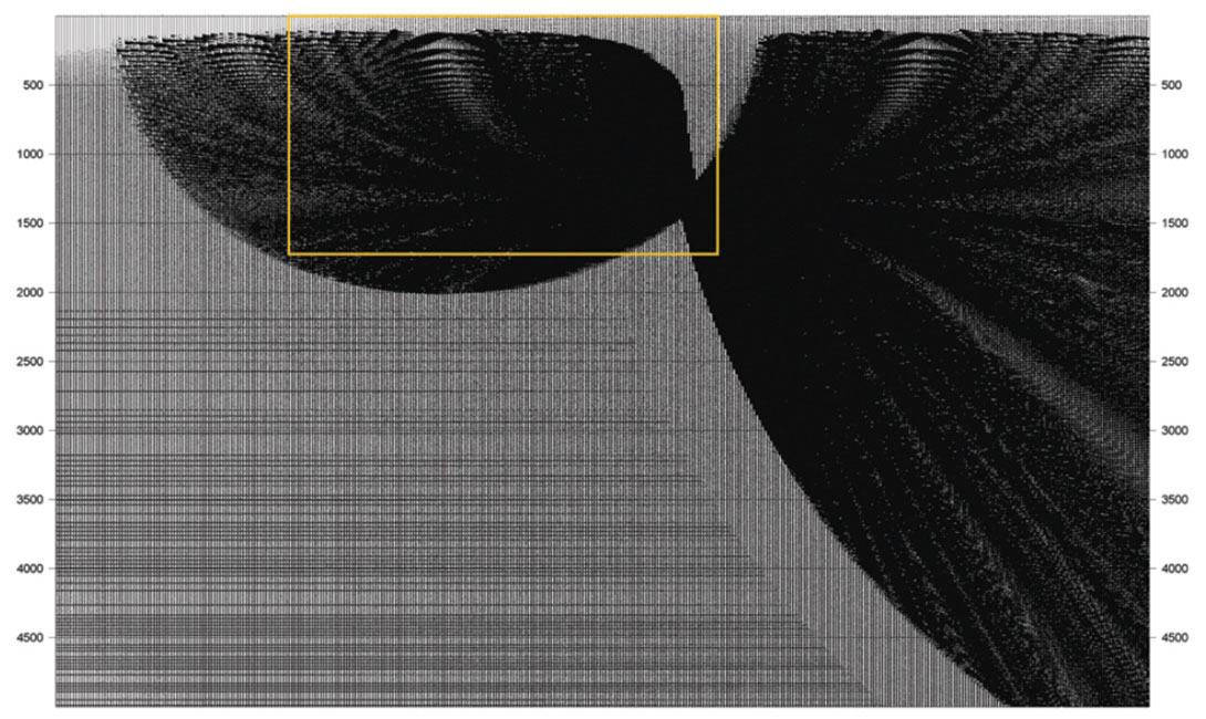
Now these wavefronts were generated by a simple spreadsheet, and the cartoon traces were drawn freehand. So there was some artistic license taken. To confirm the integrity of the cartoons, the same constant-offset geometry was used to drive a bona fide, industry-standard Kirchhoff migration routine in generating the responses of the point diffractor. The result without anti-alias filtering is displayed at high gain in Figure 7. Its overall appearance is consistent with the colored display from the spreadsheet. Figure 8 shows a zoom of the Kirchhoff result – plotted at lower gain. Let’s look again at a bin that is a fairly good distance away from the diffractor point. This bin should have approximately zero amplitudes. Shown on the left in Figure 9 is a zoom of that trace. It looks like the cartoon of the unfiltered trace that was shown earlier. That is, it is riddled with artifacts.
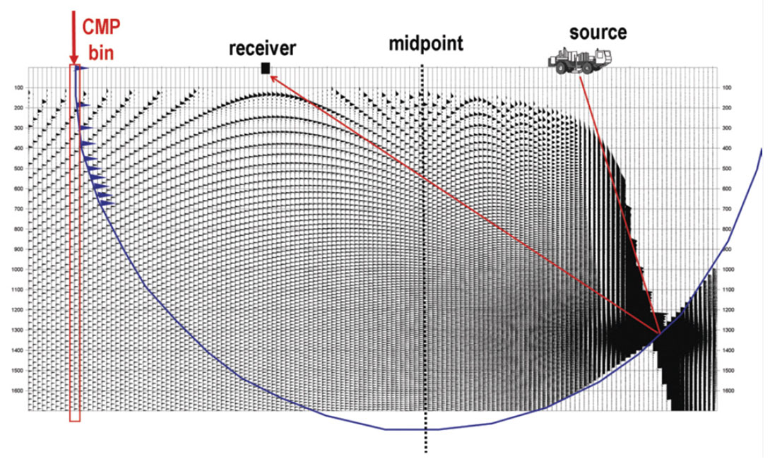
Shown on the right in Figure 9 are the data from the same bin with anti-alias filtering applied. The parameterization used was the default setting for that bin size in the Kirchhoff migration program. It was similar to settings discussed by Abma et al. (1999). As intended, we see that the alias-induced artifacts are now almost completely gone. However, this cleanup comes at a cost. The removal of high frequencies from the flanks of migration operators sacrifices some aspects of resolution. So we need a way to quantify this. We will now return to the West Texas example to show one such way.
Quantifying resolution – the sampled case
Although the seismic survey being designed for West Texas was 3D, the modeling experiments described here were 2D. The geometries mimicked inline, near-cable slices from the candidate 3D designs. The source positions were identical in the two plans, but there was a simplification on the receiver side that distinguished the two experiments. Each receiver “group” was composed of just one single sensor. So the geometry that yielded the 80-ft CMP intervals used 160-ft receiver intervals, and the geometry that yielded the 40-ft CMP intervals used 80-ft receiver intervals. The impact of arrays on resolution will be discussed later in this paper.
The modeling workflows started with placing a solitary spike at the 3.0-second target level. It was convolved with a sinc function that had an FMAX of 100 Hz. Then using a depth-dependent velocity function from the survey area, the diffraction surface for every source-sensor pair was generated. Next, the data from the two designs were migrated using a prestack Kirchhoff algorithm. The migration program’s default settings for anti-alias filters were used. So of course that means that the migration operators for the 80-ft CMP scenario were dip filtered more heavily than those for the 40-ft CMP case. After the migration, the 80-ft CMP data were interpolated to a 40-ft grid to simplify comparison of the two data sets.
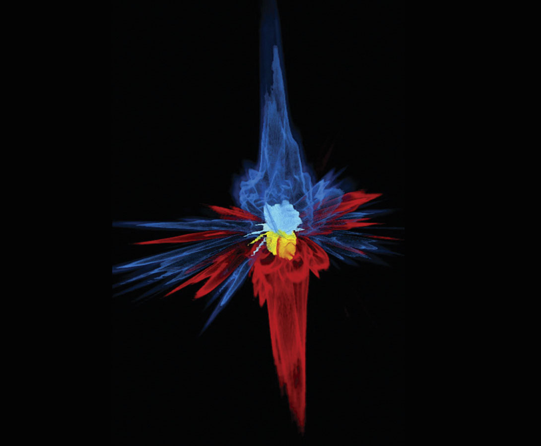
Since these results were obtained by numerical computation of the Kirchhoff integral using sampled data, we will refer to these spatial wavelets as numerical spatial wavelets. (Numerical spatial wavelets can look quite complex – especially in the case of 3D modeling. The modeling in the West Texas study was 2D, but an example of a numerical spatial wavelet from the bona fide 3D modeling done in another study is shown in Figure 10.)
So a good visual way to evaluate the resolution is actually not to look at the response from one point diffractor. Instead, it is helpful to look at the combined response of two closely spaced point diffractors. By varying the distance separating the two points in repeated experiments, a visual determination can be made concerning the lateral resolution.
In the experiments conducted for the West Texas study, the point diffractors were spaced apart at distances of 80 ft, 120 ft, 160 ft, 200 ft, 240 ft, and 280 ft. The results from the case when the point diffractors were 160 ft apart are shown in Figure 11. We see that the 40-ft CMP geometry was able to resolve the points, but the 80-ft CMP geometry was not. Indeed, the 80-ft geometry could not resolve the points until they were approximately 280 apart.
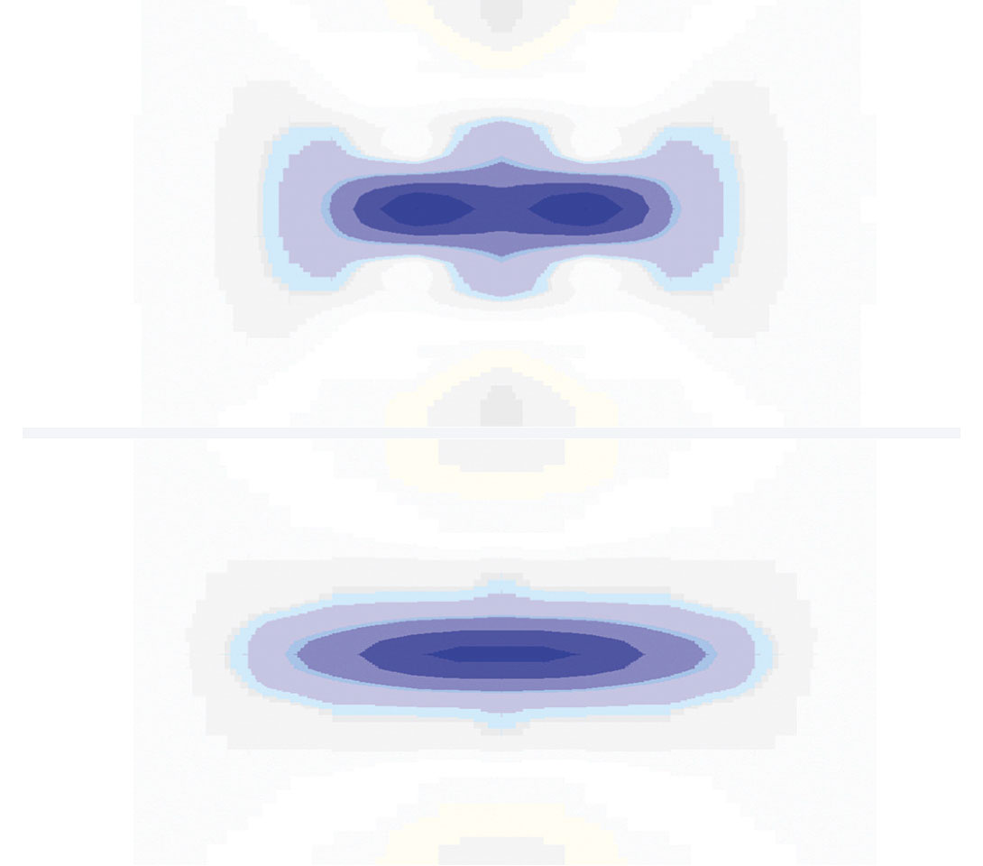
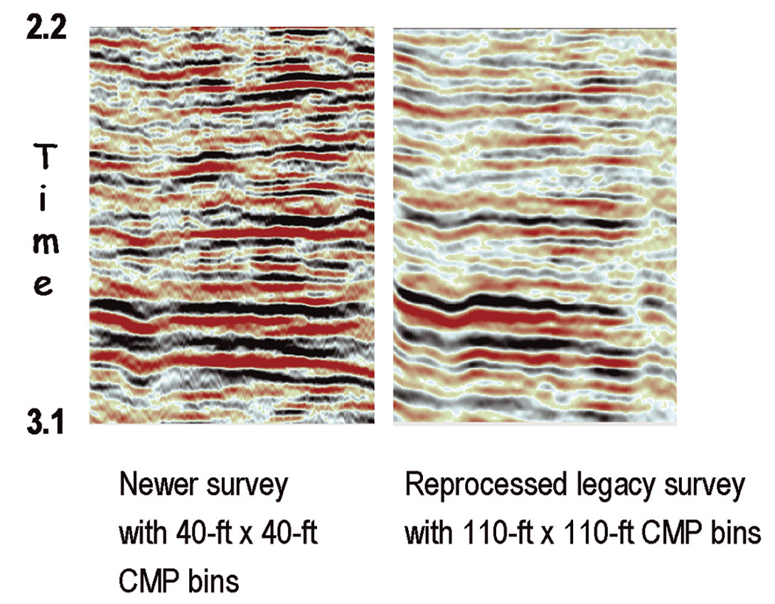
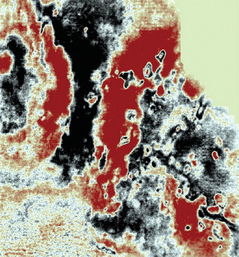
Therefore what we have said is that for the case of 100-Hz data and a temporal TMAX of 5 seconds, the best lateral resolution that could be expected for infinitely well-sampled, prestack migrated reflections from the 3.0- second target was 102 ft. For the case of a survey design that yielded CMP bins with a 40-ft dimension, the resolution was 160 ft (or perhaps a little bit better). And in the case of a similar design that yielded CMP bins with an 80-ft dimension, the resolution was only 280 ft. So the decision was made to use the 40-ft x 40-ft CMP geometry in the new 3D survey. Figure 12 shows the comparison of a snapshot from the new survey versus the same location from the reprocessed legacy survey. These are prestack time-migrated data at the deep zone of interest. The legacy acquisition used a 110-ft x 110-ft CMP design. The resolution benefit from the smaller bins is evident. In fact the full benefit in the newer data is not fully exposed because the traces there were decimated for the purpose of display comparison. The benefit of the denser sampling used in the new survey is even more evident in shallower sections. For instance, karsted zones are very clear in the shallow time slice shown in Figure 13. Of course readers might guess that a large channel-count system would be needed to acquire all of those densely sampled traces. Indeed, the new survey used 18,432 live channels per shot record. The legacy survey was acquired by a conventional system. There were 1,344 live channels in that program.
By the way, the vibrator sweep length in the new survey was 8 seconds. So in conjunction with the 5-second listen time, there was an opportunity to perform extended correlation and thereby increase the effective aperture. Indeed, this was tried in our modeling experiment. Correlating to a TMAX of 11 seconds increased the theoretical dip aperture from 55 degrees to 76 degrees. This enabled the lateral resolution to be improved approximately another 20%. However, playing such games would not have been practical in the real program because the actual surface area of the seismic survey did not include enough real estate to support that spatial aperture.
Something else that should also be brought up is that there is an opinion shared by some geophysicists working the West Texas area that it is okay to sacrifice lateral resolution for the sake of improving continuity. The combination of using larger arrays, larger CMP bins, and performing migration after stack rather than before is the seismic recipe they prefer. The lure is that the trace smearing associated with that sequence can mask footprint artifacts and noise problems. This, in turn, can allow autotracking routines to run more smoothly.
Regardless of the degree to which that opinion has pragmatic merit, there is no doubt that arrays wield an influence on resolution. So even though we said earlier that this paper will not look at noise issues, we will indeed look at the array issue because the spatial sampling aspect of it has direct relevance on signal. So that is what we will do next.
Other factors that compromise resolution – arrays
The two biggest threats to resolution that are caused by arrays come from intra-array statics and intra-array moveout. The top panel in Figure 14 shows a window of a representative singlesensor record from a 2D line that was recently acquired in the Williston Basin – a prolific basin that straddles the Canada/USA border. The window captures the main reservoirs of interest – including the Middle Bakken. A time-dependent gain function has been applied to compensate for spreading losses. But otherwise, this is a raw record. The sensors were laid out in a linear fashion. The maximum source-receiver offset on either side of the symmetric spread was 20,000 ft. The sensor spacing was 10 ft.
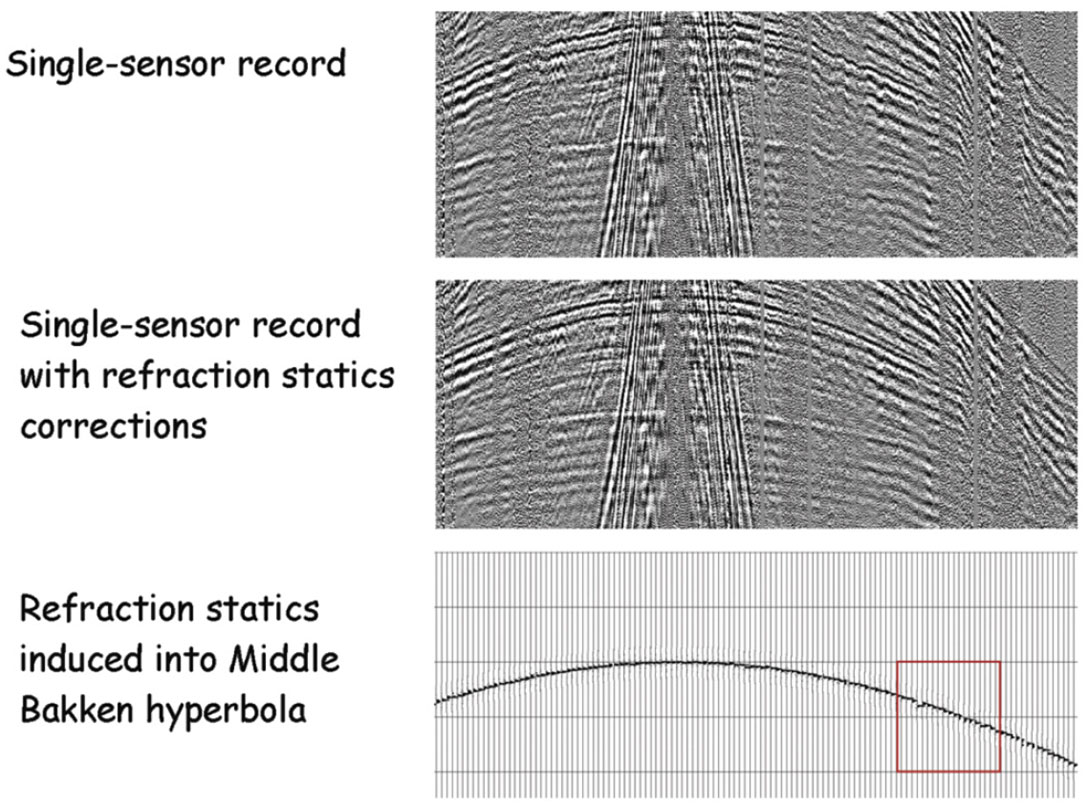
Undulations in the reflection curves clearly show the presence of near-surface static anomalies. Indeed, some of the undulations have wavelengths that are almost as short as the array lengths used in legacy surveys – namely, 165 ft. The first breaks were picked and fed into a refraction statics program. The middle panel in Figure 14 shows the same record after the single-sensor statics corrections were applied.
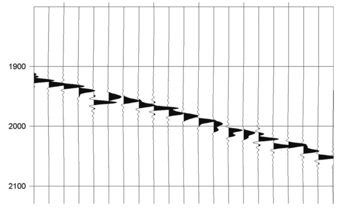
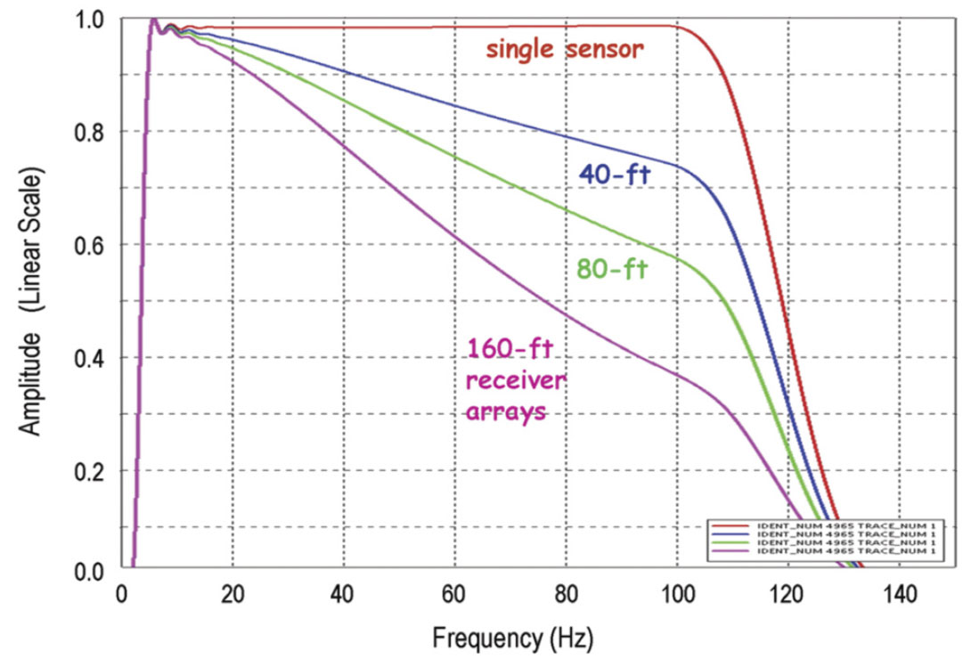
Next a synthetic hyperbolic reflection was computed for the Middle Bakken reservoir. A 4-120 Hz Klauder wavelet was used to simulate the correlated sweep that was used in the field acquisition. The exact geometry of the real shot record was used for the synthetic. The statics that were computed from the real data were then induced into the perfect, synthetic hyperbola. The bottom panel in Figure 14 shows the window of the staticsridden reflection that corresponds to the real data windows above it. A zoom of a small portion of that synthetic is displayed in Figure 15. The statics fluctuations are significant with respect to the broadband nature of the wavelet. The trace spacing in the display is still 10 ft. However, group forming was conducted to simulate three other records – one with 160-ft receiver arrays, one with 80-ft arrays, and one with 40-ft arrays. The record with 160-ft arrays mimicked the popular legacy geometry, while the 80-ft arrays and 40-ft arrays mimicked the group forming options considered for the Williston Basin in today’s singlesensor surveys. (In the case of single-sensor surveys, the ground roll is most often addressed via some sort of velocity filter operation. This can be very successful because the dense spatial sampling of the single sensors does not allow the noise to alias. After that, the data can be group formed. This could be for the simple purpose of reducing the total volume of data while still maintaining sampling adequate for imaging signal.)
After the group forming, NMO correction was applied to all four synthetic records – including the single-sensor record. And then each record was stacked using a mute function that was selected from the real data. Figure 16 shows the normalized amplitude spectra of the stacked traces. The objective was to preserve frequencies up to 100 Hz because the reservoir is quite thin. We can see that the effect of intra-array moveout and intra-array statics take a toll. At 100 Hz the conventional 160-ft array geometry preserves only 1/3 of the amplitude – compared to the single-sensor result. (Note, the mute was tight enough to prevent NMO stretch from being a significant factor. Otherwise the single-sensor result would have shown amplitude degradation at high frequencies too.)
So advances like single-sensor technology (with point sources) have aided the quest for resolution by preserving frequency content through the data conditioning steps that take place prior to migration. But actually this is just one link in the resolution chain. If any of the other links fail to keep the frequencies needed, then deterioration of resolution still takes place. One of those other links has already been discussed. That was the impact of the CMP bin dimensions. We will revisit that issue now briefly to cover one final point.
The influence of CMP bin dimensions on resolution – a revisit
In modeling experiments from another study, a wedge model was placed at the depth of the zone of interest. The horizontal side of the wedge was on the top. The migrated reflections from the dipping plane beneath it clearly showed the dependence of both lateral and temporal resolution on CMP bin dimensions. However, the temporal frequency range of the migrated reflection from the horizontal top side kept full bandwidth – regardless of bin size. Perhaps this should not have been surprising. The anti-aliasing operation inside the Kirchhoff migration routine filtered only the flanks of the operators, not the base. So for the case of an infinite planar boundary that has a constant reflection coefficient, no frequencies are lost.
So what this means is that the common practice of performing a spectral whitening step at the end of data processing can indeed whiten flat events, but it is not likely to improve the resolution of dipping events much without sacrificing the signal-to-noise ratio, nor is it likely to sharpen truncations of flat events. (Of course, sharpening such truncations is something we would like to see when interpreting stratigraphic plays.) In order to offer a simple demonstration of this assertion, we return to the case of the Williston Basin.
Once again, we called upon the method of modeling and then Kirchhoff migrating two neighboring point diffractors – but this time we considered only the simple scenario of the zero-offset section in a 2D line. The point diffractors were placed at the depth of the Middle Bakken reservoir. Figure 17 shows results for the test case when the distance between the diffractors was 240 ft. We selected one situation in which the points were already well resolved before any additional whitening, and one situation in which the points were not.
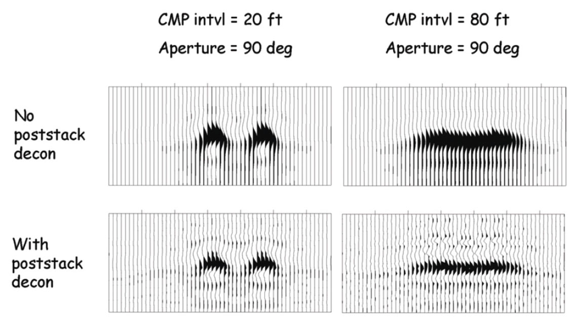
The upper left display in the figure shows the result obtained when the CMP interval was 20 ft and the migration aperture allowed up to 90 degrees. This is the case where the points are well resolved. The lower left display shows data from the same experiment after a post-migration, zero-phase spiking deconvolution step was executed. We see that the temporal resolution improved a bit, but there is no essential change to the spatial resolution. The upper right display shows the result obtained when the CMP interval was 80 ft and the migration aperture was again 90 degrees. In this case, the points are not well resolved. The lower right display shows the result after the application of the spiking deconvolution. Again, the temporal resolution improved, but the lateral resolution remained unchanged. The points were still inseparable to the eye.
Different results would have been obtained by performing the whitening step before the migration. But whatever the case, in order to produce crisp spatial resolution we still would have needed to address the spatial sampling requirements – rather than just whiten the temporal spectra.
Concluding remarks
Geophysicists in data acquisition strive to make their operations as efficient as possible. Key in this regard is to balance the source effort with the receiver effort. So for instance in land vibrator surveys, we do not want the vibrator drivers to be waiting on the movement of ground equipment, nor do we want the geophone layout and pickup teams to be waiting on the vibrators. Similar to that, we tried to show here that we should try to balance the efforts for both temporal and spatial resolution.
For instance, extraordinary efforts for putting high-frequency energy into the ground can be wasted if the spatial resolution is not brought into harmony with the temporal. This is because spatial resolution and temporal resolution are very much intertwined. One of the key factors influencing both of these is spatial sampling. Spatial sampling refers to many domains including source point intervals, sensor intervals, array dimensions, and even offset ranges, dip apertures, and so forth. And indeed these topics were at the heart of our discussions. We tried to demonstrate methodologies that are available for quantifying the impact of those sampling parameters on resolution.
Many of the points made concerning the spacing of elements were valid for sources as well as sensors. Indeed, there are examples now in the industry of successful surveys that called upon both dense source sampling and dense receiver sampling. Continuous recording systems enable the dense source effort to be implemented, and high channel-count systems enable the dense receiver effort to happen. Conducive to the use of these survey designs is free and open access. Consequently, most of such case histories come from the desert environments in the Middle East and North Africa. In North America, such access is usually not available – especially in the case of source points. Therefore, the examples in this paper favored the high channel-count, single-sensor situation.
As we said at the outset, the scope of this paper was limited to discussions of how spatial sampling relates to considerations of signal (not noise) in land surveys. However, most of the findings carry over nicely into the marine world. Indeed in that offshore arena there are additional intriguing issues related to things like uncertainty in source- and receiver positioning. And yes, such issues are analyzed too via modeling in survey preparation studies.

Acknowledgements
The authors would like to thank our colleague and senior geophysicist, Larry Stanley, for his assistance in checking the integrity of the geophysical software packages used in this study. And we would like to thank him for preparing some of the more challenging displays too.




Join the Conversation
Interested in starting, or contributing to a conversation about an article or issue of the RECORDER? Join our CSEG LinkedIn Group.
Share This Article