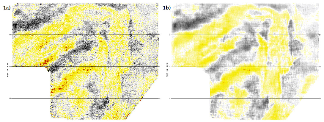
In recent years, 5D interpolation has become a very popular method for regularizing seismic data before 3D prestack migration. In addition to its main purpose of reducing the generation of migration artifacts due to irregular spatial sampling, 5D interpolation also has the very beneficial sideeffect of attenuating acquisition footprint during the interpolation process. An example is shown in Figure 1. The reason for why footprint attenuation occurs during 5D interpolation has been the subject of some debate. The footprint could either be attenuated because the noise or signal causing the footprint has been correctly interpolated and then regularly sampled within all CDP’s, or it could be attenuated because the signal or noise causing the footprint has not been interpolated correctly and therefore is reduced in the final image. In this article we examine the fidelity of the 5D interpolation of a real data example and show (with the aid of a new 5D interpolation quality control tool called 5D leakage) that footprint has been attenuated because the interpolation has been interpolating correctly in some parts of the 3D volume, and paradoxically enough, also because it has not been interpolating correctly in other parts.
Acquisition footprint is a type of noise, so we are always pleased to see footprint being attenuated. However, we would prefer to see footprint attenuated because the source of the footprint has been regularized across all CDP’s, not because the interpolation has worked badly. The point is that interpolation ideally should not be used explicitly as a form of noise attenuation. A perfect interpolator, such as a sincfunction interpolator (Karl, 1989), is said to be perfect (zero error) because it is able to interpolate both signal and noise perfectly. In fact there is nothing in a perfect interpolation algorithm that distinguishes between signal and noise. As far as a perfect interpolation algorithm is concerned, the data is all just signal.
All forms of 5D interpolators are capable of producing excellent results, but they are nevertheless imperfect in real 3D seismic data sampling scenarios. All forms of 5D interpolation (MWNI (Trad, 2009), ALFT (Xu et al., 2010), rank reduction (Trickett et al., 20) incorporate some sort of sparseness or simplicity constraint on the solution in order to interpolate a fully sampled 5D output wavefield from a relatively small number of input samples of the full wavefield. Whatever signal or noise is not sparse (i.e. sparse in the sense that the algorithm requires for correct interpolation) will be imperfectly interpolated. The danger, therefore, is that some complex parts of the signal may be attenuated during the interpolation process.
So why is acquisition footprint actually attenuated during 5D interpolation? Is it because the data is being correctly or incorrectly interpolated? Without knowing whether the noise or signal that causes the footprint has been correctly or incorrectly interpolated, we cannot answer this question with any certainty. In order to answer questions such as these, we have come up with a method for measuring the error that occurs during 5D interpolation (Cary and Perz, 2012a,b). We call this measure of the error “5D leakage”. The 5D leakage is measured only at input trace locations because it is computed by using just the newly 5D interpolated traces to interpolate back into the original input traces locations. The difference between the true input traces and the interpolated estimates at those same input locations input is a simple measure of the 5D interpolation error. Once these 5D leakage traces are computed, they can be stacked and viewed in various ways, including time slices of the CDP stack of the leakage traces.
Acquisition footprint usually appears as a regular pattern of linear artifacts, or a mesh pattern, on time slices of 3D stacks, such as in Figure 1(a). Acquisition footprint is not an indication of the true subsurface geology. Instead it resembles some aspect of the acquisition geometry, such as the shot or receiver layout. The many causes of acquisition footprint have been investigated extensively (e.g. Hill et al., 1999). A likely reason for the strong footprint that appears in the shallow parts of many 3D images is the fact that the particular offsets and azimuths that are most contaminated with source-generated or backscattered noise at early times are sampled only within every n-th CDP in the inline or crossline directions, where n is the number of CDP’s between source or receiver lines. As a result, a regular pattern of noise appears at every n-th inline or crossline.
Various aspects of reflected signal, such as residual normal moveout, can also cause acquisition footprint. For example, a multiple reflection, or a primary reflection that is not flat across all offsets due to an NMO velocity error may generate a regular footprint pattern due to the regular wavelet sampling at particular offsets within a pattern of CDP’s. Even amplitude variations with offset (AVO) on a perfectly flat reflector will generate some degree of amplitude footprint on the final stacked image due to the pattern of offset sampling within the CDP grid.
After 5D interpolation, the offset and azimuth sampling of traces within neighboring CDP’s is regularized. Regardless of whether it was some aspect of signal or noise that was the original cause of the footprint, the fact that the signal and noise are sampled identically at all offsets and azimuths within every CDP after 5D interpolation will make the regular footprint pattern disappear. At least that is the argument, if you believe that 5D interpolation is interpolating the full wavefield (i.e. signal plus noise) perfectly.
The trouble is that, even though the 5D interpolated data may look excellent, we have already established that 5D interpolation is not perfect, so there is at least some possibility that footprint is being attenuated because the aspect of the noise or signal that caused the footprint has not been correctly interpolated. To generate footprint, you require two things: (1) a variation of the wavefield with offset (and/or azimuth), and (2) a somewhat regular, but sparse, sampling of offsets and azimuths within CDPs. To attenuate the footprint with an interpolation method, you need to do one (or both) of two things: either remove requirement (1) with an imperfect interpolation, or remove requirement (2) with a good interpolation/regularization method. How is one to know which of these two situations is causing the footprint attenuation in any particular case?
An examination of the accuracy of the interpolation, as measured by the 5D leakage, can answer this question. If the aspect of the wavefield that is causing the footprint is being correctly interpolated, then the stack of the 5D leakage traces will not contain any sign of the footprint. This would be the case if the source-generated noise, or the multiple, or whatever signal or noise was the origin of the footprint in the first place was being correctly interpolated into all new trace positions. The source of the footprint would then also disappear from the 5D leakage. On the other hand, if the footprint does appear in the 5D leakage, then we know that the aspect of the signal or noise that was the origin of footprint was not being interpolated correctly. Footprint in the 5D leakage implies a poor interpolation. Absence of footprint in the 5D leakage implies a good interpolation.
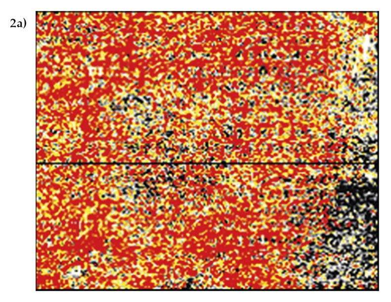
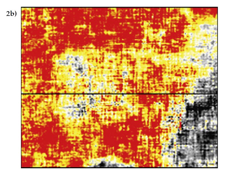
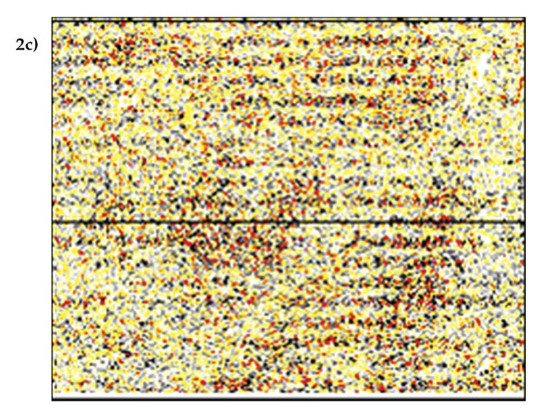
Figure 2 is taken from the shallow section (300ms) of the 3D volume from an orthogonal land 3D dataset. The original stack shows a fairly large amount of footprint which is probably caused by some remnant of source-generated noise that has not been completed removed during processing. The attenuation of the footprint by 5D interpolation is both dramatic and beneficial to the final image. The time slice of the 5D leakage stack shows a large amount of footprint, which indicates that the noise has not been perfectly interpolated.
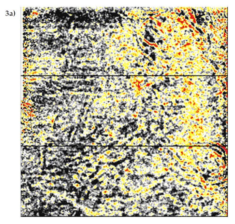
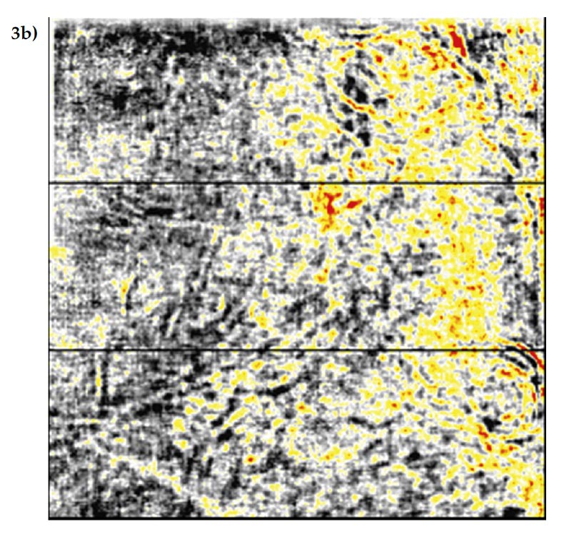
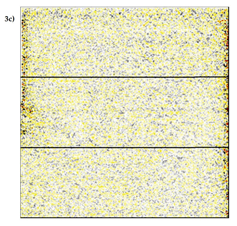
Figure 3 is taken from a deeper section (1500ms) of the same 3D volume as in Figure 2. The footprint in this case is less strong than in Figure 2, and its true cause (whether due to signal or noise) is not obvious from examining the data but it is likely due to some variation with offset in the moveout or amplitude on a primary or multiple reflection. The footprint attenuation by 5D attenuation is more subtle in this case than in Figure 2, but the attenuation is no less important at this time level because of the similarity of some of the real geologic features to the linear footprint. At this time level, the time slice of the 5D leakage shows only slight hints of footprint, so in this case, whatever signal or noise was the original cause of the footprint is being very well interpolated.
The examination of the 5D leakage in Figures 2 and 3 has enabled us to know what is really happening when footprint is attenuated by 5D interpolation. The answer in the case of this 3D volume is that footprint attenuation is occurring for two different reasons. In the shallow section, footprint was attenuated as a result of imperfect interpolation, and in the deeper section, footprint was attenuated as a result of a good interpolation.
These findings should not surprise us if we reflect on the data requirements for a good 5D interpolation. The smooth spatial variations of moveout and AVO on primary and multiple reflections can be described by relatively simple wavenumber spectra, and such simple variations in the data are well reconstructed by 5D interpolation given its sparseness assumption. By contrast, the rapid offset variations of steeply-dipping source-generated noise are less well-suited to the assumptions of 5D interpolation so we should not be surprised that this type of noise is not being perfectly reconstructed. Since this 3D dataset is typical of most land orthogonal 3D datasets in terms of its signal and noise sampling issues, we would expect to see that footprint is attenuated by 5D attenuation in many other 3D datasets for both of these reasons.
In summary, this article has examined the issues surrounding the question of why 5D interpolation attenuates 3D acquisition footprint. We have found that attenuation occurs because 1) signal in the deeper section has been interpolated and then sampled regularly in the output CDP’s and 2) noise in the shallow section has not been properly interpolated so its effect has been reduced in the final image. We have come to these conclusions based on the recently devised method of measuring 5D leakage (Cary and Perz, 2012a,b). 5D leakage has proven to be very useful not only for enquiring into this footprint attenuation issue, but also for enquiring into other important issues such as the preservation of resolution.

Related Reading


Join the Conversation
Interested in starting, or contributing to a conversation about an article or issue of the RECORDER? Join our CSEG LinkedIn Group.
Share This Article