Pressure terms clarified
Any fluid which is contained within subsurface rocks is under pressure. As is often the case in geophysics, there are many and varied terms to describe pressure. Here's a summary of commonly used pressure terms.
| is... | is also known as ... | |
|---|---|---|
| Confining pressure | The weight of the overlying rocks. The overburden pressure at any depth is the pressure which results from the combined weight of the rock matrix and the fluids in the pore space overlying the formation of interest. Overburden pressure is depth dependent and increases with depth. |
Load pressure Lithostatic pressure Geostatic pressure Overburden pressure |
| Hydrostatic pressure | The pressure caused by the weight of a column of fluid above the formation of interest, extending to the surface. The pressure in the water in pores usually increases with depth at the same rate as a simple column of water in a cylinder. |
Normal hydrostatic pressure |
| Pore pressure | The pressure acting upon the fluids in the pore space of a formation. When a rock is heated, volatiles such as water or carbon dioxide may be released as gases. The pressure that is produced by these volatiles is called the pore-fluid pressure. Overpressure, or geopressure, is talking about pore pressure. |
Formation pressure Interstitial pressure |
| Effective pressure | Confining pressure minus pore pressure. Effective pressure is the pressure which is acting on the solid rock framework. It is the effective pressure that controls the compaction process of sedimentary rocks; any condition at depth that causes a reduction in effective pressure will also reduce the compaction rate and result in geopressure. | Differential pressure |
| Overpressure | Pore fluid pressure which is higher than the hydrostatic pressure. The seismic presentations of abnormally high pressure include low P-wave velocity and low density. |
Geopressure Abnormally high pressure |
-Jan Dewar
Migration Temporal Frequency Shifting
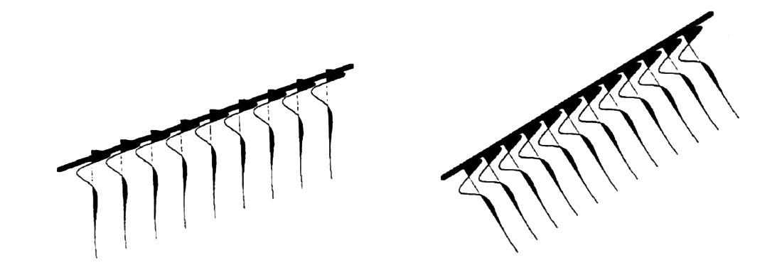
This topic is perhaps closer to being a geophysical concept, rather than a definable term. Migration shifts the temporal bandwidth to lower frequencies for dipping events while the horizontal wavenumbers are unchanged.

The frequency shift increases with increasing velocity and/or geologic dip.

As a result, the relationship between wavelet, reflectivity, and seismic data is no longer a Simple I-D convolution after migration. This means that filtering and deconvolution do not commute with migration and usually should be done before (from the course notes of Dr. Gary Margrave).

Constant velocity (15000 fps) model with dips of 15°, 30°, 45°, 60° and 75° created using a 14 Hz Ricker wavelet. (left)
Images after FK migration. Notice that the widths of the wavelets normal to the events are the same. (center)
Migrated image filtered with a 7/12-60/70 Hz Ormsby filter. (right)
(Migrated 3D Alberta Foothills data shown courtesy of Time Seismic Exchange and Husky Energy.)

Wavelets defining the steep dips are stretched temporally. (left)
Filtered 7/12-60/70 Hz after migration. (center)
No filtering after migration. (right)
(In this example Florian Romanescu of Veritas did the migration velocity analysis and demonstrated that the data should not be filtered after migration.)
- Larry Mewhort


Share This Column