This month the ‘Expert Answers’ column features a question on sparse receiver marine seismic surveys – to get to know how they are different from the conventional streamer surveys.
The experts answering the question are Eivind Fromyr (PGS), Eugene Gridnev (WesternGeco) and Todd Mojesky (CGG Veritas).
The order of the responses given below is the order in which we received them. We thank the experts for sending in their responses.
Question
Usually marine 3D seismic surveys are planned and recorded with a fairly dense grid of receiver locations. Sometimes however, 3D surveys are acquired that are source-rich, but receiver-poor, like the OBC surveys. How are these sparse receiver surveys useful and what additional challenges do they present, beyond those encountered with conventional streamer surveys?
Answer 1
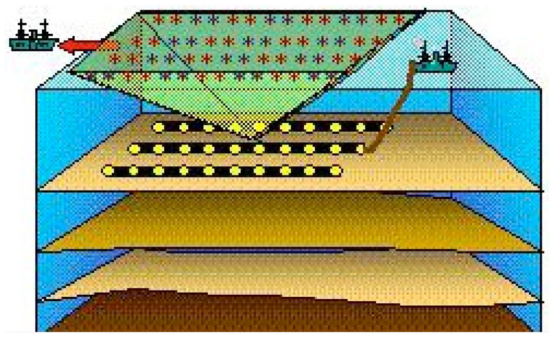
There can be a number of reasons why one may choose a stationary seabed referenced system (Figure 1) for seismic imaging.
- If the receivers are equipped with 3-component geophones, converted waves can be recorded and used in combination with conventional P-wave data for imaging and characterization. [1]
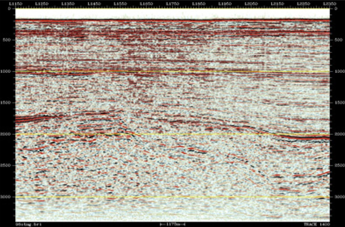
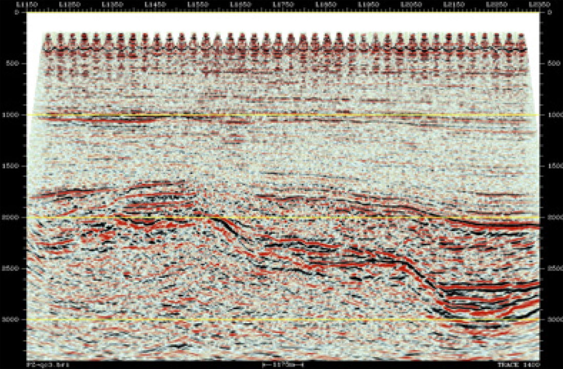
- By deploying sensors on the solid-liquid interface one can employ powerful multiple attenuation techniques using the combined vertical geophone and hydrophone recording. [2]. A data example showing the application of dual sensor summation is shown in Figure 2. [3]
- Since source and receivers are decoupled, one has much more freedom in terms of survey geometry. Up till recently it has been considered to be the only practical way to acquire wide azimuth data in the marine environment. [4]
There are broadly speaking two alternative technologies for ocean bottom acquisition, both possessing the capabilities mentioned in a) and b).
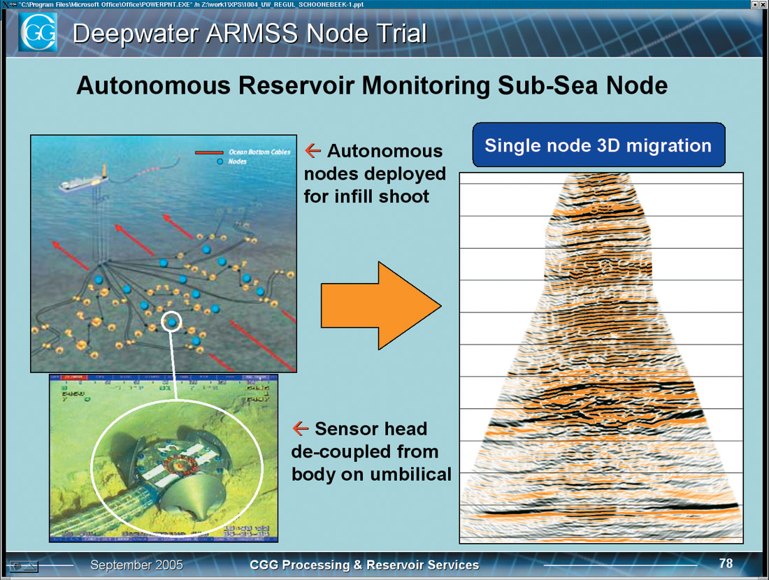
- Autonomous nodes positioned on a regular grid. Typical distances between receivers can range from 250m to 500m, depending on target depth. A wide azimuth swath of shots is normally re corded into each receiver. Depending on target depth and objectives in general, the offset can range from 3 to 8km in in-line direction and/or cross-line direction. Because of the sparseness of the receivers, the shot grid tends to be quite dense, typically 50 by 50m.
- A cable based system is deployed with typical in-line spacing between 25 and 50m with a total length between 6 and 12 km. Cross line receiver spacing may vary from 100m up to 500m, but normally it tends to be towards the higher end due to cost. Number of deployed cables can vary from2 to 6 or more. Two alternative shooting patterns can be used, a narrow azimuth swath or a wide azimuth patch. The high end version of the patch shooting alternative can approach the grid shot over nodes, but typically the shot line spacing is not as dense for the cable case.
Let us first compare the two ocean bottom alternatives in terms of operation, survey design and processing issues. It should be clear by what has been said so far that one can encounter a variety of OBC solutions, some source-rich and receiver-poor and some closer to the ratio imposed by conventional streamer surveys.
Operationally the biggest difference between a node system and a cable system is the deployment and retrieval method. Cables are deployed from a DP handling vessel and normally laid under tension. Cable systems allow rapid deployment and retrieval at speeds up to 2.5 knots. Nodes will be deployed from a DP vessel using an ROV except in very shallow water. However, due to the relative sparse nature of the receiver grid, a large receiver area can be covered simultaneously and hence the overall cost may not be significantly different between the two methods. Generally speaking the acquisition effort will be determined largely by source effort requirement and efficiency gained by having a large number of receivers active at all times. The node systems have the advantage of being easier to deploy on congested areas as well as on rugose seabed topography.
The main geophysical difference between the node concept and cables is the in-line receiver sampling. The sparseness of the node grid may present challenges in velocity determination. Since no CMP or CCP space is properly populated, the preprocessing of node data will have to be performed on common receiver gathers, which offers less choice than data with regular sampling in both source and receiver domain. It may also make AVO type analysis more difficult. Some concerns have been raised historically with respect to the robustness of wide azimuth patches, be it node recorded or cable recorded, in regards to imaging due to sensitivity to azimuthal anisotropy variation [5]. Recently more sophisticated anisotropic processing has alleviated these concerns. In some cases the narrow azimuth in-line cable design combined with dense in-line shooting is preferred due to its superior capability to suppress intra-bed multiples.
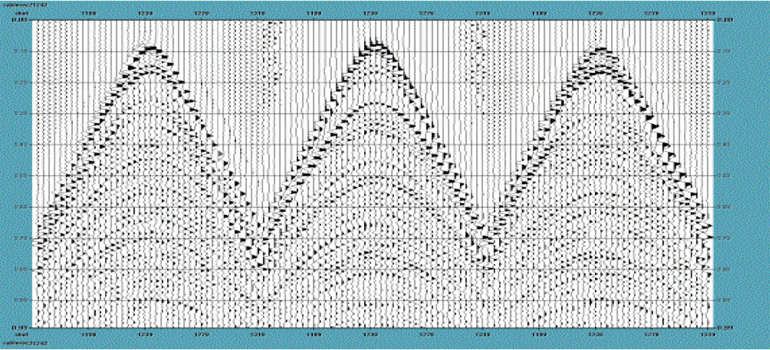
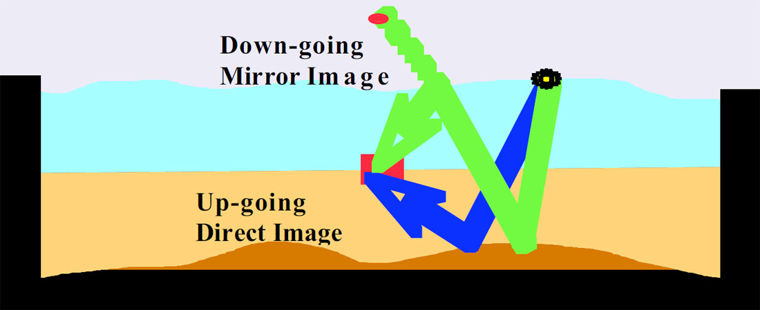
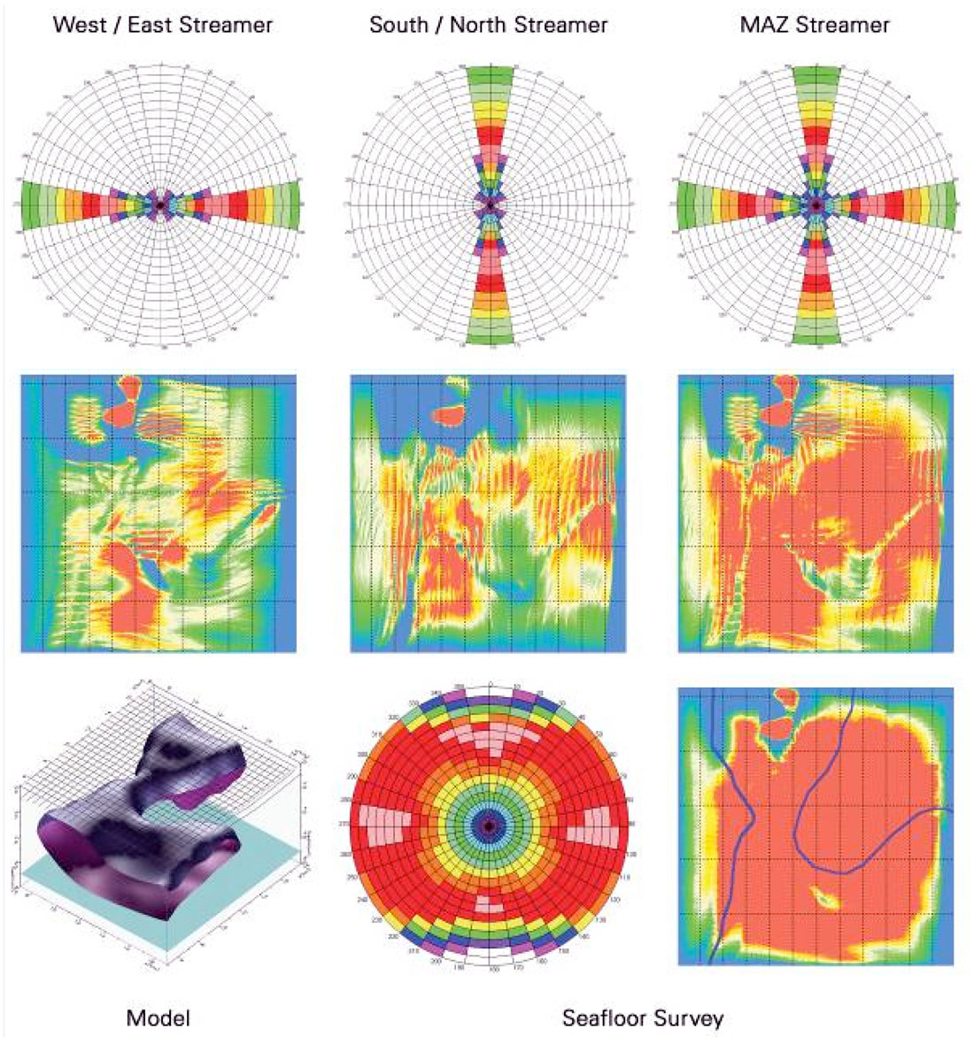
Ocean bottom sensors with a wide azimuth aerial shot domain acquisition produce 3D common receiver gathers that are suitable for shot profile imaging, assuming source-receiver reciprocity (Figure 3) [4]. From an imaging perspective this is the main strength of the method over narrow azimuth streamer solutions. Figure 4 shows the illumination difference between a narrow azimuth streamer survey, a dual azimuth streamer survey and a wide azimuth OBC survey in a sub-salt setting. Clearly the wide azimuth alternative is superior. As we will discuss below, a wide azimuth streamer alternative would give similar results to the OBC in terms of illumination. Generally speaking wide azimuth alternatives for obvious reasons are superior in that respect, with one exception; all seabed referenced systems tend to suffer in terms of imaging the shallowest part of the subsurface. This is due to distance between nodes or cables compared to typical streamer separation used in conventional towed mode. Also, since source and receivers are vertically separated one has less coverage for the same offset range. One can overcome difficulty by using both the up-going as well as the down-going wave-field in imaging [4]. Figure 3 illustrates the concept. The down-going wave-field recorded on the sea-bed contains the subsurface primary wave-field reflected at the sea-surface and as such has wider coverage.
Generally speaking one can not achieve the objectives mentioned in a) and b) by conventional streamer technology. As far as P-wave imaging is concerned, conventional streamer surveys are by definition narrow azimuth and as such have rather poor sampling characteristics in terms of minimal data sets and symmetry [6]. However, due to the high efficiency of modern multi streamer operations, Multi azimuth and Wide Azimuth streamer alternatives have emerged, addressing the objectives mentioned under c). Multi-azimuth acquisition attempts to overcome illumination deficiencies in conventional streamer geometries by acquiring the data multiple times in different directions. Wide Azimuth streamer acquisition will emulate a stationary receiver system by acquiring data with additional source vessels decoupled from the streamer spread. Multiple passes with different crossline spacing between source and receivers are required. By doing so one can construct super-gathers similar to wide azimuth ocean bottom records that are suitable for shot profile imaging [7]. Acquisition of a wider range of azimuths will improve imaging quality due to superior illumination as well as better multiple diffraction attenuation when compared to conventional streamer data [8], [9], [10].
A variety of alternative streamer solutions as well as a variety of OBC solutions have emerged and matured over the last few years. As a result there is less clear distinction between the two in terms of source-receiver sampling and therefore ability to tackle imaging challenges.
Eivind Fromyr, PGS
Houston, Texas, USA
Answer 2
The decision to deploy a particular technology on a survey is always the result of the analysis of often conflicting factors and should be made after careful evaluation of the survey objective, analysis of legacy data, and analysis of operational and economic issues.
Commercially available options available to an exploration team are primarily: surface streamer (single vessel narrow azimuth and multi-vessel wide azimuth), Ocean Bottom Cable (OBC) and Ocean Bottom Seismometer nodes (OBS).
As regards the geophysical objective, the exploration geophysicist typically would have arrived at the desired acquisition parameters during survey planning with some of the critical parameters being:
- Type of geometry for optimum imaging, e.g. is wide azimuth required by the model? The answer generally being dictated by the results of a target illumination study. Several wide-azimuth surveys have now been shot in the Gulf of Mexico over complex salt structures after extensive analyses of velocity models.
- The ability to solve the geophysical problem using P-wave only, or the need for shear wave data. Ocean Bottom Cable or nodes will typically have 4C sensors.
- Desired prestack trace density for noise attenuation.
- Spatial sampling in shot/receiver and CMP domain to avoid aliasing and provide adequate noise suppression.
- The desired record length. Together with shot point interval, record length affects the survey duration by limiting vessel speed.
- Maximum offset in all directions to capture all useable data.
- Migration aperture to insure adequate imaging of the target.
- Maximum line spacing to allow imaging of shallowest target .
Operationally, several issues can argue either for, or against, a specific acquisition approach.
- Water depths of over 1500 m currently exceed the limits of most bottom cable systems. Use of nodes has been demonstrated at depths exceeding 2000m.
- A complicated water bottom topography can argue in favor of OBS node placement vs bottom cable.
- Restrictions on placing bottom cables over pipes and anchor chains. This is often the case in mature deep water fields.
- Dense surface obstructions would typically make a streamer survey impractical
- Exact sensor placement and repeatability are important if the survey is intended as a baseline for 4D. Existing remotely operated vehicle and underwater positioning technology allows placement of individual nodes within a few meters of intended location in water depth in excess of 2000m. Latest cable control technology enhances applicability of streamer vessels for 4D applications
- OBS nodes have a finite battery life and memory capacity. Care must be taken to ensure there is sufficient recording node endurance to record data from all shots needed for maximum offset, as well as for node positioning and component rotation (needed for correct 4C processing). Typically, shots from multiple azimuths and offsets of X0.5 the water depth are needed for positioning and rotation.
Project economics related to crew productivity and daily cost, are also important parts of the process of choosing the optimum technology for the survey.
Single-vessel, narrow azimuth surveys still represent the bulk of marine acquisition. The advantages are high production, lower total crew cost, and higher reliability.
Multi-vessel acquisition schemes have been developed recently for large area (over 5000 km2) wide-azimuth streamer surveys where geophysical objectives mandate wide-azimuth geometry. Due to the nature of streamer design, sampling in the inline direction is significantly denser than in the crossline.
OBC cable surveys have significantly higher cost per CMP km due to the limited number of cables recorded each shot (typically 2-4, compared to 8-12 streamers on a conventional streamer survey).
OBS nodes are typically deployed in smaller projects (200-400 km2). A survey area would be an existing field, and the survey design would be tailored to a specific target. Node surveys require that we evaluate each unique area and acquisition parameters in order to forecast acquisition time and cost. This is due to the difficulties in accurately predicting node crew productivity due to the amount of variables involved:
- Node density is the single most important factor after the survey size. Reducing node interval will not lead to a proportional increase in the survey duration. Instead consider increasing the number of receiver patches to 3 from 2. Even if the shot density stayed the same, the added shots that will be replicated in the added seam zone between patches will reduce overall productivity.
- Shot density: shot point and line spacing. In most cases it is easier to reduce inline shot interval until vessel speeds drop to unsafe level. Shot line interval, on the other hand, leads to a proportional change in shot effort and project duration.
- Node inventory. It is ideal to shoot a job with just one receiver patch, but there are a limited inventory of nodes (1000 on a crew is typical)
- Size of survey. Determines how many node patches will be required.
- Maximum offset required in inline and crossline directions. Consider a survey with multiple node patches. Having to extend the shot patch to satisfy the maximum offset requirement leads to an increase in number of shots that are duplicated in the seam zones between patches
Is there a place where OBS nodes are actually the best?
If we had to formulate a short answer to the question “How are these sparse-receiver surveys useful and what additional challenges do they present, beyond those encountered with conventional streamer surveys?”, it would be “they are useful wherever the survey design, operational restrictions, and economics, make them the best solution in terms of projected data quality and cost”.
Based on information available to date, a strong case for node system would be:
- Relatively small surface area
- Heavily obstructed surface and subsurface
- A strong case for 4C processing
Eugene Gridnev
WesternGeco
Answer 3
N.B. As you’re hopefully all aware, CGG and Veritas DGC have merged since Satinder’s formulation of these questions. Before I begin, I’d like to add a small disclaimer that any answers reflect this author’s views, and not necessarily those of CGG, Veritas DGC, nor CGGVeritas (I don’t think I’ve missed anyone). OK, to begin:
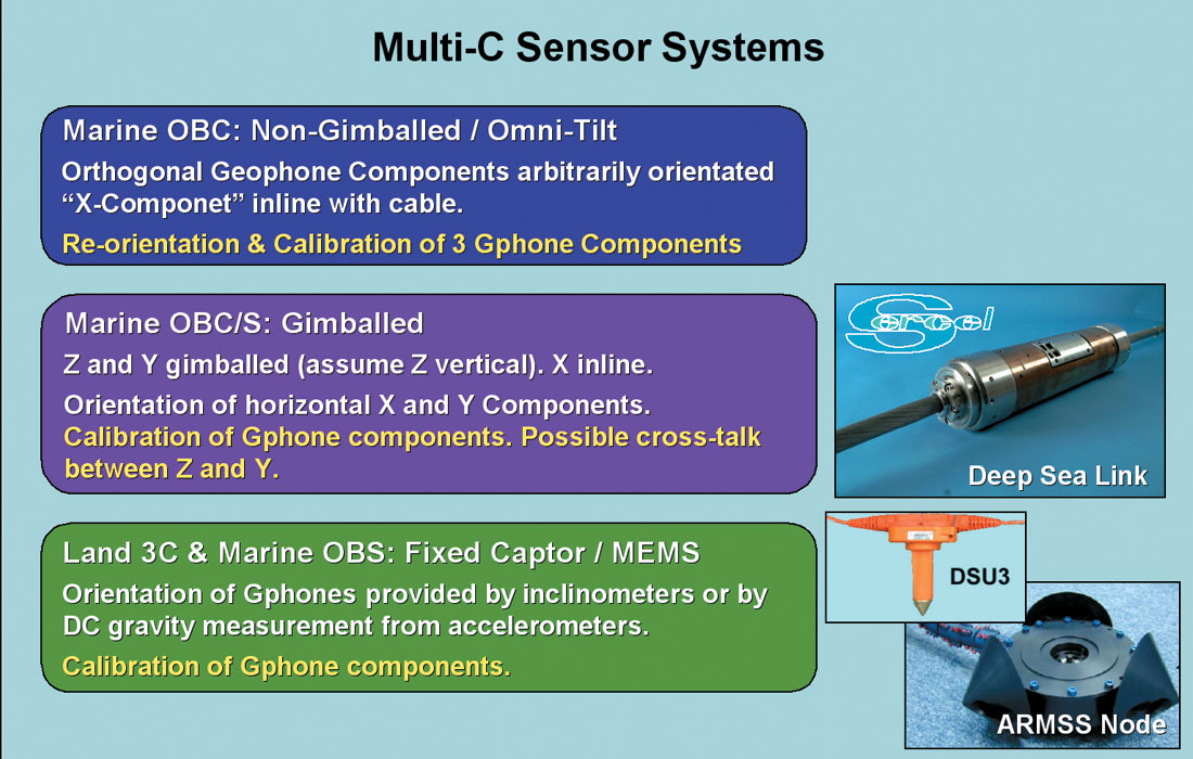
There are quite a few flavours of Ocean Bottom Seismic (OBS) surveys, depending on the type and deployment of the receivers: OBC, single sensor nodes, 2C, 4C, gimballed…. OBS surveys typically use multi-component receivers, and each individual sensor is either a directional geophone (vertical or horizontal) or a unidirectional hydrophone. Figures 1 and 2 following show some examples.
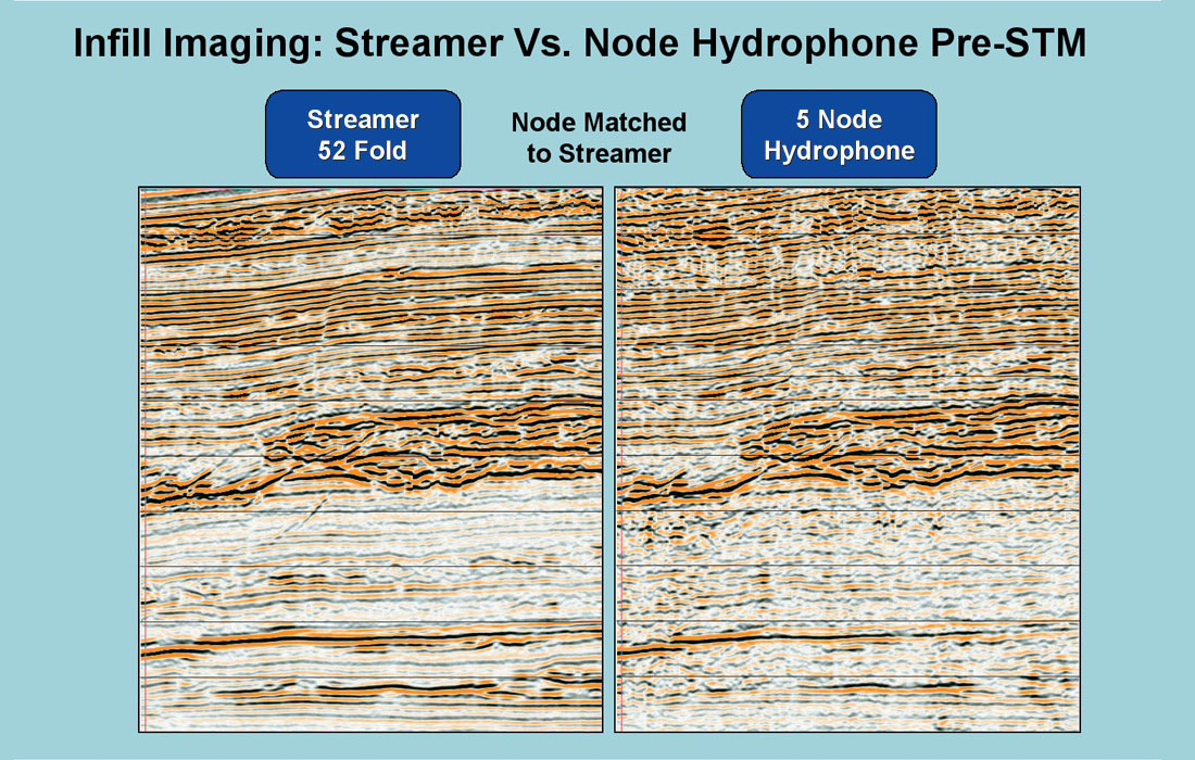
Receivers on the seafloor are an expensive commodity, turning OBS into some of the most costly marine acquisition possible. They are typically used in shallow water conditions (for example near-shore Beaufort Sea), around obstructions (platforms), and wherever shear (converted wave) recordings are required. While sparsity is a consequence of economics, it often has little impact on image quality (Figure 10). I’d say that anybody who’s worked with the typical 3D WCSB data is already used to sparse acquisition, anyway.
OBS Surveys can bring a lot to the table. An added bonus, of course, is the guarantee of wide-azimuth coverage (unlike the virtual inline recording of “normal” surface marine surveys). OBS technology has become a prime tool for detailed offshore reservoir delineation. In fact, the bulk of multi-component acquisition monies are spent on OBS surveys. With the advent of simultaneous P-P and P-S pre-stack inversion, detailed and accurate rock properties can be directly estimated. In general, these marine P-S data typically have at least the resolution of their equivalent P-P data, and are much more sensitive to the rock matrix and for instance fractures. It just takes a bit of processing to extract that information.
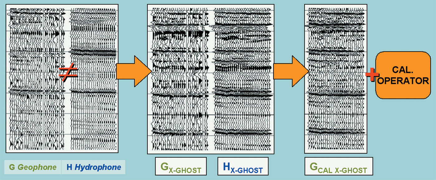
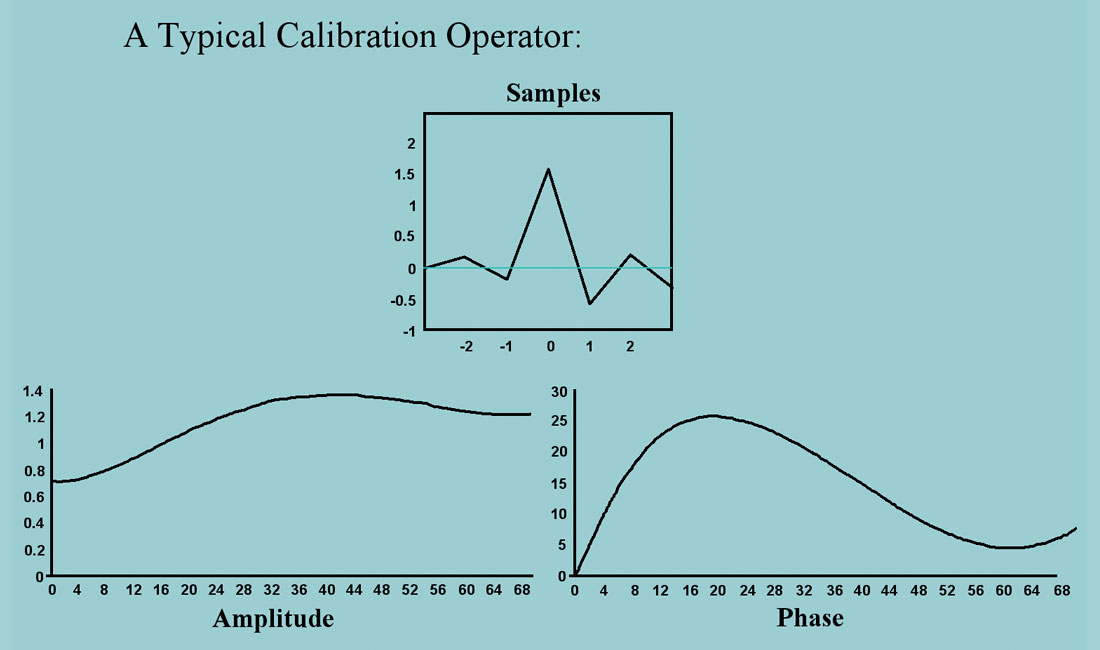
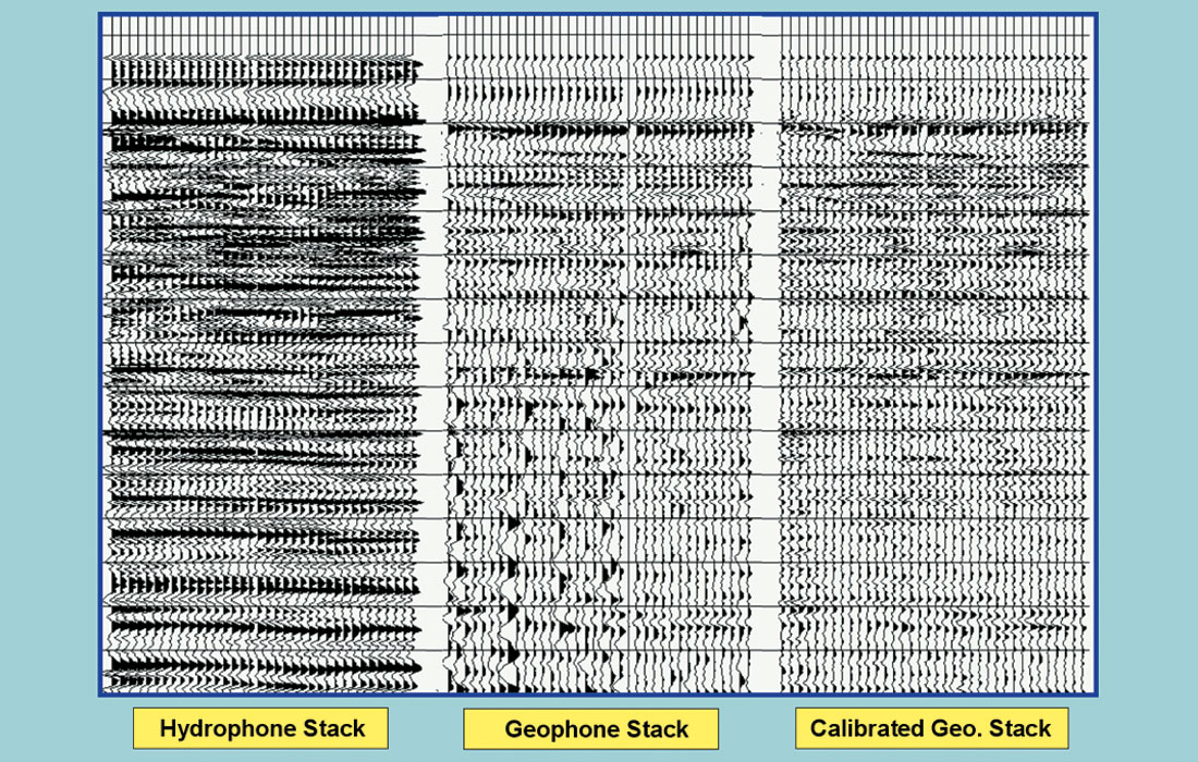
Let’s take a quick tour of some of the processing involved in a dual-sensor (hydrophone and vertical geophone) recording. The first step, getting the precise location of each receiver, is easily addressed via standard first-arrival positioning tools. The calibration of each sensor is perhaps the most crucial step in processing: we need to bring all sensors and coupling responses in line together. As we know, hydrophones measure pressure changes (a scalar quantity), whereas geophones react to velocity variations (directional vector quantities), and so are themselves directional. The hydrophones typically have a high frequency bias, whereas the geophones have both a strong low frequency bias and a strong noise element due to coupling issues. They all have to be matched-up in their responses to get anything quantifiable out of the recording. Now, each will record the unwanted receiver-side water-column reverberations (receiver “ghosts”), but with different polarities. With proper processing, and utilizing the vertical geophone and hydrophone, we can actually eliminate this strong ghosting or ringing in the records. The terminology typically used in this matching process is called “cross-ghosting”, whereby we first model a geophone ghost to add to the hydrophone record, and a hydrophone ghost to the geophone record. This requires an accurate water depth, extracted at the processing stage. A calibration operator can then be derived to apply to the geophones to match their very different frequency and phase responses (Figures 3 to 5). This brings us to one of the industry’s most common OBS catchphrases: “PZ summation”. Summing the hydrophone (P) to the matched geophone (Z) gives us the up-going energy with the ghost neatly cancelled out. Given that the waterbottom is rather flat, one can also use these phones and their relative polarities together to remove pegleg (multiple) energy, as well.
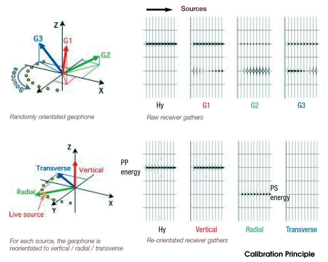
That described a typical two-component processing flow. However, four-component sensors (three geophones and one hydrophone) are now the norm. Here, orientation and calibration become more critical, especially so for non-gimballed systems. But as it turns out, by using a different approach the entire problem can be solved in one go. Instead of using first arrivals for analyses and calibration, actual reflected and converted data are used. Using a simple propagation modeling approach, one can best fit a frequency-dependent composite vertical geophone that, in turn, best fits the hydrophone data, while at the same time stripping out all converted wave energy. In this way, the data that would be recorded by a true vertical phone is created from all three of the geophones. Instead of being a problem, having those extra packaged geophones gives us the edge in producing a better P-P product. Similarly, radial and transverse geophone composites can then be automatically extracted using the same approach. The resulting components all have matched wavelets, and the PP and P-S responses are nicely segregated (Figures 6 to 8).
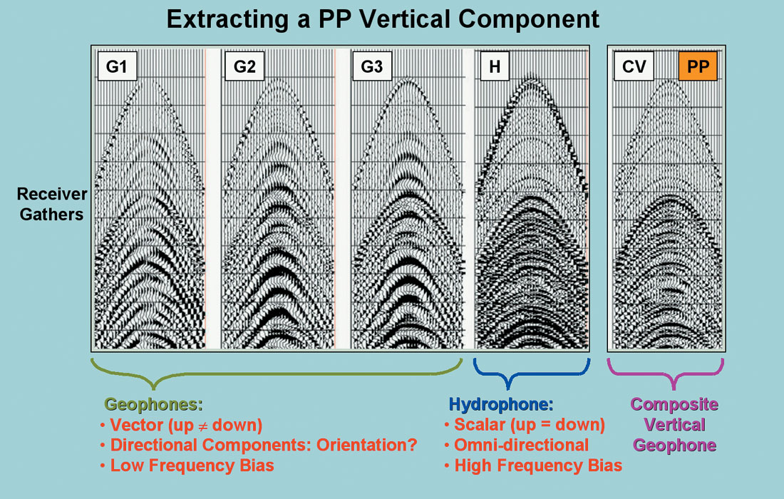
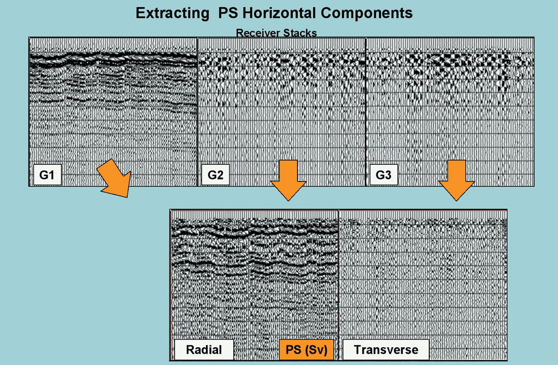
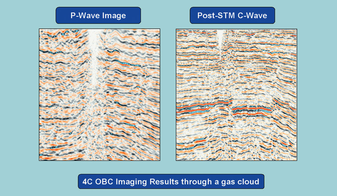
For the high cost of these surveys, we’d better be able to extract some darned good data! In fact, some pretty impressive imaging can be produced using the P-S converted wave energy, which is sensitive to the lithology and not to the pore fluid. This means we can get spectacular results imaging through gas clouds and flat spots and see reservoir sands that are “transparent” to P-wave (Figure 9). As for P-wave data, it fairs pretty well. In Figure 10 we can evaluate a five-fold OBS P-wave section in a head-to-head comparison with that from a 52-fold surface streamer.
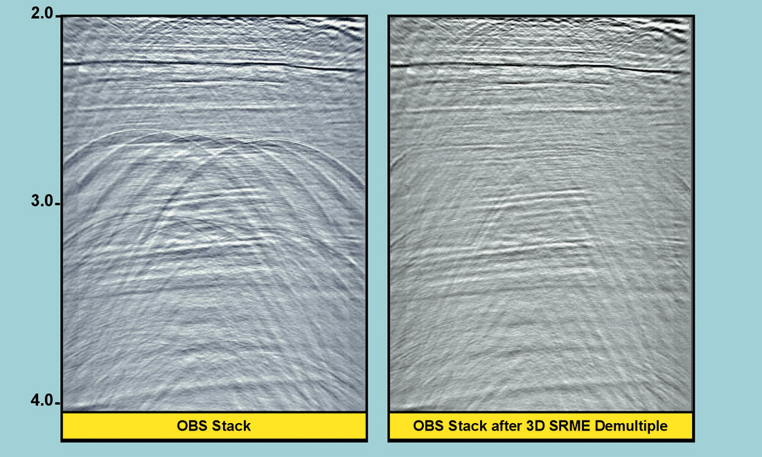
Lastly, one historical problem with OBS recordings is the difficulty in applying “ SRME” (Surface Related Multiple Elimination) to them. This powerful demultiple method is an “automatic” surface-consistent algorithm, that requires a shot where every receiver exists, and vice-versa (usually created via interpolation in the processing steps). SRME has made the images from our “surface” marine acquisition substantially better in deep water settings However, in OBS recording with the source near the top of the water, and the receivers well below, the surface consistency that conventional SRME requires is not upheld and we’ve got a problem. A new 3D methodology, based upon wave-propagation modeling techniques instead of the original surface-consistent auto-convolutional version, neatly gets around that issue. I’ve attached a figure from last year’s SEG presentation by A. Pica, along with the abstract reference.
Todd Mojesky
CGGVeritas, Calgary


Share This Column