This issue of the RECORDER features questions on marine seismic data acquisition, and looks for answers to the use of multi-streamers, multi-source acquisition, sampling of wavefield in the crossline direction, feathering of streamers and repeatability of surveys and the technology trends in this field.
The ‘Experts’ answering these questions are Thorbjørn Rekdal (PGS), Guillaume Cambois (CGG), Helmut Jakubowicz (Veritas), Nick Moldoveanu (WesternGeco), Tony Curtis (WesternGeco) and Manus Ola Eiken (Statoil). We thank them for sending in their responses to our questions. The order of the responses given below is the order in which they were received.
Question 1
Has the use of multi-streamers and multi-sources in marine seismic data acquisition led to improved resolution and image quality? Could you furnish examples to illustrate your answer?
Answer 1
Before the question is answered, it might be of interest to briefly review how the marine streamer acquisition has developed. In the beginning of the 1980’s, 3D streamer acquisition was typically acquired with bin-sizes of 50m in the cross line direction and 12.5m in the inline direction, in a single-source single-streamer configuration. Around the mid-eighties, the dual source configuration was introduced. The extra source array was exploited to increase the sail-line separation from typically 50m to 100m, without reducing the cross-line sub-surface sampling. The follow up deploying two-streamer two-source operations and longer streamers implied further improvements in efficiency and/or sampling density in both the cross-line and inline direction. In the late 1990’s dual source configurations with more than 10 streamers were regularly applied with sub-surface bin-sizes of 6.25m in the inline direction and 25m in the cross-line direction. Also, the maximum offset acquired has increased in the same period.
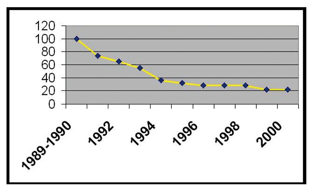
It is rather easy to demonstrate that multi-streamer multisource acquisition has increased the efficiency of acquiring 3D surveys. Figure 1 shows that the cost is reduced about a factor five for a survey of 1500 km2, over a decade between 1990 and 2000, despite the fact that the trace density has increased significantly over the same period. The main reason is the introduction of more streamers with a corresponding increase in sail-line separation.
It is a bit more difficult to quantify the improvements in quality going from single-streamer to “many”-streamer operations, since there are often other improvements contributing to the higher quality image. However, it is beyond doubt that higher trace density and smaller bin-sizes, made affordable by towing more streamers, has improved the seismic image quality. Higher frequencies are aliased when the subsurface is too sparsely sampled in either the inline or the cross-line direction. Aliased data create noise during the application of any multi-channel processing operation. The implication is a trade-off between reducing noise and preserving the frequency content in the final image.
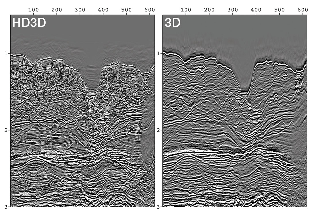
Figure 2 shows a data comparison after migration between a survey shot in 1991 (data courtesy of Shell) and a new survey shot in 2002 (courtesy A. Long, PGS) over the Malampaya field, offshore Philippines. The 1991 survey was shot with a dual-streamer configuration, and the bin-size was13.33mx26.67m. The new survey was shot with a twelve-streamer configuration and the bin-size was 6.25mx12.5m. The fold was increased from 34 to 54. The trace density increased from 95000 traces/km2 to 691000 traces/km2. This figure shows close-up of the sections in the shallow part. Significant improvements are also observed deeper. Both data sets have recently been processed. Though there were other factors in the acquisition contributing to the overall improvement, it is clear that a significant portion is contributions from the higher trace-density and improved cross-line sampling. For more details about this data example and discussions around the topic of improved sampling, I will refer to Andrew Long et al’s article in the January 2004 issue in the CSEG RECORDER.
– Thorbjorn Rekdal
Answer 2
The use of multi-streamers and multi-sources has greatly improved 3D marine seismic data acquisition productivity, but it has generally resulted in lower quality seismic images. Multi-sources (generally dual) mean flip-flop shooting, which decreases fold, aliases multiples and introduces other undesirable acquisition patterns. Multi-streamers mean increased minimum-offset for some bins, and increased noise from the diverging side wings. Single-source single-streamer acquisitions offer much better sampling, but with such low productivity (in terms of square kilometers acquired per day) that 3D acquisition cost would be prohibitive. We would not have seen such an uptake in 3D marine seismic activity if it were not for the multi-sources multi-streamers technology.
– Guillaume Cambois
Answer 3
There is no doubt that multistreamer and multisource acquisition has helped provide significant improvements in the resolution and image quality of marine seismic data. However, although from a technical perspective this is certainly due to the finer crossline spatial sampling afforded by these methods, by far the biggest impact of these technologies has been in increasing the availability of 3D data. Indeed, the original rationale for multisource and multistreamer acquisition was to reduce acquisition costs, and, if it were not for the efficiencies deriving from these techniques, it is debatable whether 3D marine data would be in as widespread use as they are today. The fact that 3D data have now replaced 2D data as the standard geophysical tools for exploration and development is powerful testimony both to the efficiency of these techniques, and the improvements obtained through 3D imaging.
Aside from providing increased access to the inherent benefits of 3D imaging, most of the improvements in resolution and image quality obtained from multisource and multistreamer marine data derive at least as much from related technologies as they do from any virtuoso towing feats. In particular, whereas multiple sources and streamers can increase the overall density and spread of the coverage, these would not in themselves contribute to higher resolution unless complemented by accurate positioning information and data processing. In this regard, improvements in positioning technology over the last ten years have been considerable, and this has certainly allowed modern data processing to provide demonstrable improvements in resolution. This is particularly evident in time-lapse (“4D”) data, for which individual 3D surveys are effectively snapshots, not only of the geological changes in and around a reservoir, but also of the seismic acquisition technology used to image them. In my experience, time-lapse comparisons of data that have had the benefit of more highly resolved positioning information are always more detailed and compelling than those that use older data where the positioning accuracy is less satisfactory. Furthermore, experience from time-lapse studies shows that positioning is the single most important aspect for maintaining integrity between different datasets, and this has in turn led to corresponding improvements in the images we can obtain from individual 3D surveys.
– Helmut Jakabowicz
Answer 4
Yes. Multistreamers and multisources have led to improved seismic resolution and image quality.
The most important geophysical benefit of multistreamers and multisources acquisition is improvement of the crossline sampling. With multistreamers a smaller cable separation is affordable and this means smaller bin size in the crossline direction, which, could translate into improved horizontal and vertical seismic resolution. The bin size for a 3D development seismic survey could be as small as 6.25 m inline and12.5 m crossline. Figure 3 illustrates the difference between a 3D survey acquired with four streamers, 4800-m length, 53.3-m streamer separation, single source, processed at 13.3-m x 26-m bin size, and a 3D survey acquired with eight streamers, 8000-m length, 100-m separation, dual source, interleaved shooting method, acquired with a 6.25-m x 12.5- m bin size and processed at 12.5-m x 12.5-m bin size. The acquisition parameters differ by more than just the number of streamers, and processing is not identical, but the improvements in seismic resolution that can be obtained today with multi-streamers multi-source acquisition are relevant.
The use of multiple streamers increases the azimuth range, a benefit for fractured or structurally complex reservoirs. With a wider spread and denser crossline sampling, 3D multiple attenuation methods could benefit because these methods require better crossline sampling (source interval equal with the receiver interval in x and y directions) and enough crossline aperture to record 3D scattered multiples.
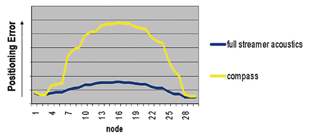
An additional advantage of multistreamer acquisition is the improvement that can be obtained in receiver positioning. With multiple acoustic networks installed along the cables, a more accurate navigation solution can be derived because the solution accuracy is a function of the spread width.
Are there any negative aspects of multistreamers and multisources acquisition? Yes, some disadvantages are:
- Multisources acquisition degrades the sampling in the midpoint and receiver domain, and this may affect the seismic processing results in these domains, particularly coherent noise and multiple attenuation. Also the CMP fold is reduced, and consequently, the signal-to-noise (ambient) ratio decreases. For this reason, not more than two source arrays shooting in flip-flop mode are used on a routine basis.
- Multiple attenuation algorithms in commercial use (e.g. SRME) are 2D, and, for this reason, narrower spreads are more suitable for the application of 2D algorithms to 3D data.
- Multiple streamers multiple-sources generate crossline offset variation and irregular illumination, which could affect the imaging results. Prestack imaging algorithms in commercial use today are designed for narrow azimuth data, and sampling irregularities could affect the results by introducing artifacts in the data.
These disadvantages could cause problems to processing methods that assume properly sampled data, offsets, and azimuths, in the domain where a particular processing step is performed. However, improvements made recently in data processing algorithms – especially in data regularization and 3D multiple attenuation – mitigate some of the negative aspects of multistreamer multisources acquisition (Kleemeyer, 2003).
What about the economics of multistreamers multisource acquisition? We could say without hesitation that this was the main driver for developing highly efficient marine acquisition systems, resulting in reduced 3D marine acquisition cost. This contributed to the discovery of huge hydrocarbon reserves in the last decade.
– Nick Moldoveanu
Question 2
Efforts to increase the sampling of the wavefield have focused more on the inline direction. Improved data quality would require such efforts in the cross-line direction as well. Is this being addressed?
Answer 1
Compared to the inline direction, cross-line sampling is rather sparse in conventional surveys. Inline bin-sizes are typically 6.25m and cross-line bin sizes are typically 25m. Both source and receiver positions are rather dense in the inline direction, but sparser in the cross-line direction. The distance between the shot-lines has increased as a consequence of increasing number of streamers to improve efficiency. Reduction in cost of large regional surveys by towing more streamers has been the major driving force in the 1990’s for marine streamer seismic. In the recent years, new towing technology has made it possible to tow many streamers with a reduced streamer separation. Up to 16 streamers have been used with a streamer separation of 50m. Several surveys have recently been acquired with both 50m and 37.5m streamer separation. This reduces the natural bin-size in the cross-line direction, while maintaining the efficiency. There is a clear trend that more surveys are acquired with improved cross-line sampling.
Increasing the number of streamers without increasing the sail-line separation (hereafter called overlap-shooting) is a survey configuration that has several advantages. It can be used to improve illumination in complex geology if all the data is utilized.
– Thorbjørn Rekdal
Answer 2
Efforts to decrease cross-line sampling have focused in two directions. (1) Reduce streamer spacing: standard lateral distance between streamers is 100 meters, but it can be reduced to 50m, or even 37.5m. However, the longer the streamer, the more difficult it gets to maintain a short distance and avoid entangling. Typically, short spacing limits streamer length to 4 to 5 km. (2) Shoot the survey in multiple directions: shooting the survey twice, in-line and cross-line, guarantees that both directions are equally sampled. Perhaps not the most cost effective solution, but by far the simplest! It also helps subsurface illumination by providing multi-azimuth acquisition.
– Guillaume Cambois
Answer 3
Although crossline sampling is naturally critical for 3D data, it never attains the same intensity in marine data as is deemed necessary for the inline direction. For example, whereas the inline sampling provided by modern seismic streamers is equivalent to using groups of hydrophones with an interval of 12.5 m (or less), the current “state of the art” in the crossline direction is equivalent to using point receivers at intervals of 25 m (or more!). Furthermore, this seems unlikely to change anytime soon, and, while some would argue that marine data should be sampled even more finely within a seismic streamer, nobody has yet either offered or proposed a system that would offer the same degree of sampling between seismic streamers as is available within them.
Of course, in principle, there is no reason the sampling requirements for the crossline directions should be different from those for the inline direction. However, spatial sampling for seismic data acquisition is always a compromise between what is desirable in theory, and what is achievable in practice. In general, it is much easier to provide relatively fine spatial sampling within a streamer, than it is to provide equivalent sampling in the crossline direction. In particular, while some of the crossline sampling deficiencies can at least partially be addressed through the use of multiple sources and streamers, there are limitations both on how many sources can successfully be used within a single configuration, as well as how close streamers can be towed together. Thus, further improvements in crossline sampling can only be achieved either by interleaving neighbouring sail lines, or in processing through interpolation. Indeed, my own view is that successful spatial sampling begins with careful survey design, and should incorporate information from existing well-sampled (often 2D) data. This allows spatial sampling to be studied semi-empirically, and affords the opportunity to assess and balance the need for actual field measurements against the benefits (and limitations) of modern interpolation techniques.
Before leaving this question, I would like to mention two other sampling issues that I believe will become increasingly important over the next few years. In particular, multiples are a constant problem in marine data, but the sampling typically available in 3D surveys provides insufficient shot coverage in the crossline direction for wave equation Surface-Related Multiple Elimination (SRME) to be effectively applied in 3D. As a result, I believe we will see the emergence of what I call “3D SRME-friendly” acquisition schemes. Similarly, there is another important undersampling problem in terms of azimuthal coverage, and this is a particular concern for so-called “illumination” in areas with complicated velocity variations. Thus, for sub-salt imaging, marine data are normally limited to a relatively narrow range of azimuths, and are therefore deficient in parts of the wavefield that can contain essential information for imaging the underlying structures. Again, there is a need for improved acquisition methodologies to address this issue, and I am aware of work that is being carried out on this problem. However, it is apparent that any solution to either the problems of 3D SRME or optimum illumination will inherently require an overall increase in acquisition effort.
– Helmut Jakubowicz
Answer 4
The answer is again positive, and, as we have seen from the previous response, the main geophysical benefit of multistreamers multisources acquisition is the improvement in the crossline sampling. The industry addressed the crossline sampling from two directions: improvements in marine technology and survey design.
Seismic technology
The seismic industry made a tremendous effort to develop marine acquisition technology that enables efficient and safe operations using multistreamers and multisources. I will mention two important developments.
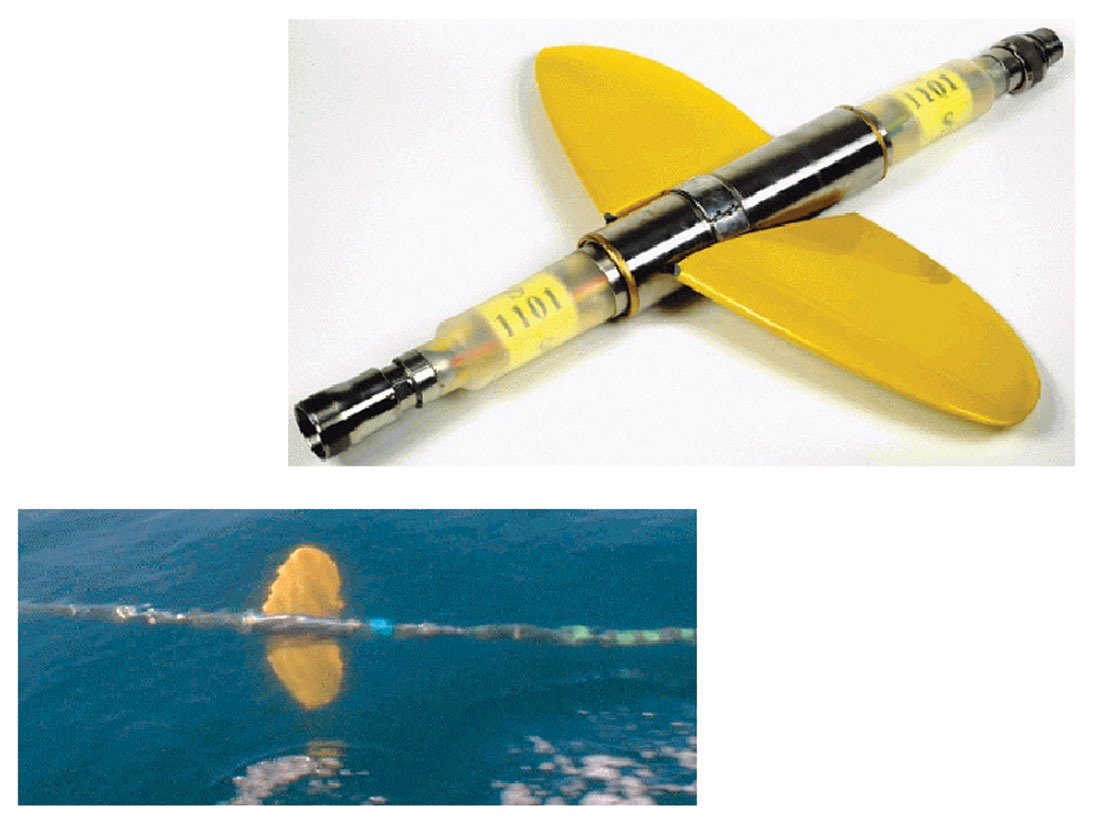
1. With up to 80 km of streamer in the water, sometimes during adverse weather, streamer control is vital for safe marine operations. To provide stable streamer separation, a Monowing* deflector system was developed by WesternGeco based on high-tech “-aircraft wing design-”. The Monowing is a large, highly efficient, controllable single hydrofoil wing, which is towed vertically, a few meters below the surface). It generates enough “lift” to pull streamers out to a 1600-m spread width. Currents or other operational effects can result in streamer separation different from nominal. The operators onboard can monitor Monowing positions and make adjustments as required. In addition to streamer control by Monowing technology, we introduced cable steering for Q-Marine* system. This is achieved with the Q-Fin* steering devices (Figure 4) for controlling streamer separation and position by steering the s t reamer horizontally and vertically. The benefits of streamer steering are: maintain constant streamer separation even in the presence of the strong currents, compensate for feather angles up to +/- 3 degrees, less operational risk in obstructed areas, safer deployment and retrieval of the streamers and improved acquisition repeatability for 4D surveys.
2. The results of any 3D marine seismic survey must be very accurately positioned, and for this reason, the in-sea positioning of receivers and sources is very important. GPS technology has become the industry standard to position sources and tail buoys.
Checking of GPS hardware and software performance is also critical, and for this reason, a GPS verification product was developed by WesternGeco called Integrity Monitor, which directly checks onboard, during the acquisition, GPS position results. GPS measurements give us the accurate location of the front and end of the streamers, but the cable shape also has to be determined very accurately, and this is performed with acoustic networks installed along the cables. The novelty introduced by WesternGeco in terms of acoustic networks is in deploying acoustic sources along the cable, typically every 800 m, that emit a high-frequency encoded acoustic signal, which is recorded by the regular hydrophones inside the streamers. Thousands of ranges recorded by the hydrophones are transmitted to the navigation system and the navigation software uses these ranges and the GPS measurements to determine the accurate position of each hydrophone along the cable. In this way, positioning accuracy has been improved (Figure 5).
Survey design
3D survey bin size is determined by seismic resolution requirements and this is a function of dip, subsurface velocity, and maximum required frequency. Generally, steep dipping and complex structures require smaller bin size. The need for high-fidelity data for reservoir characterization and development has also led to smaller bin size, and consequently to high-density 3D data in order to improve seismic resolution and the signal-to-noise ratio after 3D prestack migration. The signal-to-noise ratio after 3D prestack migration, is a function of the total number of traces contributing to prestack migration output, and this number is larger if bin fold and number of bins within migration aperture are larger. A smaller bin size in the crossline direction could be achieved with a smaller streamer separation or by using the interleaved shooting method. The shooting direction for the interleaved method could be parallel with the previous direction or antiparallel. Choosing between parallel or antiparallel directions could have an effect on acquisition footprints.
A Gulf of Mexico Q-Marine 3D survey acquired and processed with a 6.25-m inline x 12.5-m crossline bin size illustrates that is possible to get detailed reservoir information. An integrated reservoir characterization study was performed on the seismic dataset that included hybrid inversion.
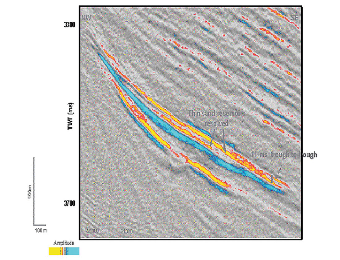
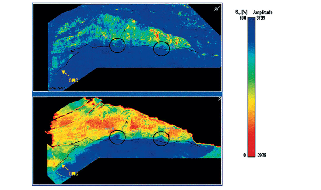
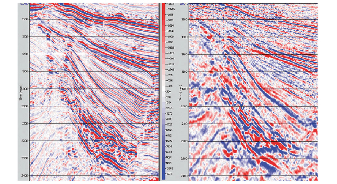
In Figure 6, a seismic section through the reservoir, illustrates vertical seismic resolution in terms of thin beds and permeability barriers. Figure 7 shows a comparison between an amplitude seismic map and a saturation map derived from seismic data. On the saturation map, we can notice clearly the coning effect induced by the productions wells. This information that can be obtained from seismic data is very valuable for reservoir development.
– Nick Moldoveanu
Question 3
What are the technology trends in marine seismic data acquisition?
Answer 1
Improving the survey acquisition cost-efficiency will continue to be a major driving force for technological improvements in marine seismic data acquisition. However, we will see a change in the trend from a continued increase in sail-line/shot-line distances to improvements in sampling. There is also a demand for increasing offset for deeper reservoir imaging. The new trend for improved sampling is driven by all or some of the following factors:
- Need for improved seismic resolution in the reservoir
- Improved illumination to obtain a better image
- Suppression of multiples by improved sampling
- Introduction of “true” 3D seismic processing technologies
- Improve detection of changes in the reservoir in timelapse seismic
- Need to increase offset
Denser sampling will improve the signal-to-noise ratio, and will be an important factor in obtaining higher frequencies in the seismic. To fully take advantage of the improved sampling, high-fidelity processing techniques should be applied.
Complex geology might require multi-azimuth data to be adequately illuminated. Two techniques to obtain this with streamer seismic are shooting in different directions or increasing the number of streamers without increasing the sailline separation (overlap-shooting). The multi-directional shooting has been successfully applied on at least two surveys. Experiments have also demonstrated that multi-azimuth data inherently suppresses multiples from diffractions.
Overlap shooting is becoming popular in time-lapse (4D) marine streamer acquisition. The overlapping streamers are then used to be able to select traces from base and monitor surveys with same source-receiver azimuth. It has been demonstrated that this technique significantly improves repeatability.
Alternative geometries such as overlap shooting and interleaved shooting may reduce the need for conventional infill shooting. Infill lines are shot between sail-lines when the coverage is not obeying the required specifications. Using overlap shooting, the problem with feathering is significantly reduced, since full coverage is easier to obtain.
Surface Related Multiple Elimination (SRME) is a technique that has successfully been applied in a 2D mode for some years. Recently, results using 3D SRME have been published. 3D SRME is capable of removing multiples where the geology varies significantly in the cross-line direction. It is demonstrated that the method will benefit from larger cross-line receiver aperture (more streamers) and denser cross line sampling of shot-lines.
Multi-azimuth data also drives a need for azimuth dependent velocity field and imaging techniques that will take these into account. This might further drive a demand for multi-directional acquisition.
Since the mid1990’s, a significant effort has been driven by seismic service companies in developing seafloor seismic acquisition and processing of converted waves (C-waves). This acquisition technology is more expensive than marine streamer seismic. However, there are fields where the p-wave image has proven to be superior to streamer seismic. This is mainly contributed to three factors: Multi-azimuth sampling, multiple removal using dual-sensor summation, and significant increases in trace density. BP is currently testing permanent installation of receivers on the seafloor for seismic monitoring on the Valhall field. This is an exciting new area of marine seismic.
– Thorbjorn Rekdal
Answer 2
Perhaps the most promising trend is wide-azimuth acquisition for illumination purposes. Marine streamer 3D acquisition is by essence multi-2D and consequently only samples one azimuth. Some structures cannot be imaged by a single azimuth, which means that standard marine 3D acquisition may leave shadow zones in the data. This has been observed many times, especially in the Gulf of Mexico where complex salt structures make subsalt imaging challenging. To circumvent the problem the survey can be shot in multiple directions (see above) or using ocean bottom cables (OBC), which provide a land acquisition like sampling. Since both solutions are quite expensive, a lot of research has been devoted to designing original acquisition geometries that would allow wide azimuth re cording with standard streamer vessels. The SMAART JV (a research joint venture associating Mobil, BP, Chevron, Texaco and BHP) was very active in this domain but was sadly dismantled before it could put its ideas into practice. However, the interest still remains.
– Guillaume Cambois
Answer 3
Although the data quality of marine seismic data has continued to improve over the last few years, this has largely been achieved through incremental changes. It is therefore likely that the marine seismic technology of tomorrow, will be very similar to that which we use today. Of the technologies that are either already established or in development, I believe we will see a wider range of acquisition geometries, not least to address the concerns listed above. Similarly, I expect further improvements in positioning technology, together with more data-driven and problem-driven ways of assessing coverage. I also expect improvements in recording equipment, including the adoption of solid streamers as the standard for seismic cables, as well as the possibility that they will contain a new generation of sensors. Otherwise, at a more mundane level, tape may soon (finally!) be superceded by other forms of data storage.
On a more speculative level, there will probably be an increase in seabed recording, especially if the equipment costs can be reduced. This would not only offer a solution to some of the sampling issues described earlier, but is perhaps also a more natural solution for time-lapse applications. More importantly, cheaper seabed recording may also open up access to multicomponent data in the same way that multisource and multistreamer techniques have made 3D data more widely available.
Finally, there is always scope for radical new developments. At the top of my wish list would be a fully controllable source, with the resulting possibility of addressing sampling challenges through pseudo-orthogonal sweeps. Certainly, while it will be hard to replace, much less displace, our trusty airgun arrays, there could be many advantages in finding an alternative. Indeed, if there is one trend we must cherish and continue to foster, it is that we must continue to be open to change. As the Greek philosopher Heraclitis said, “He who does not hope for the unexpected, never finds it.”
– Helmut Jakubowicz
Answer 4
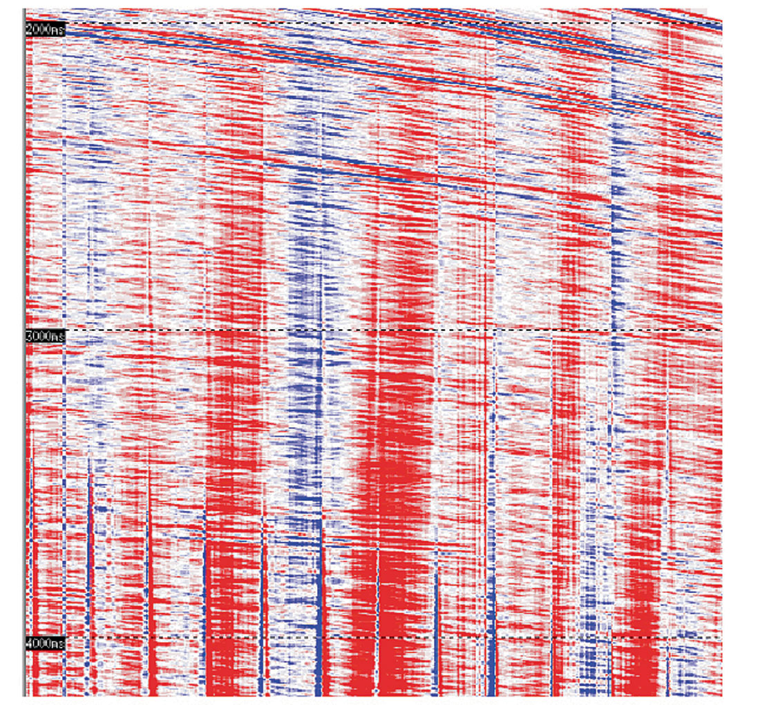
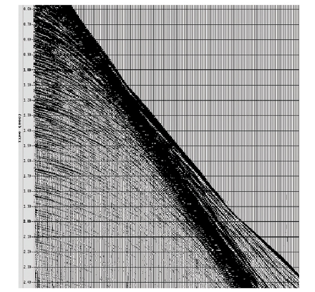
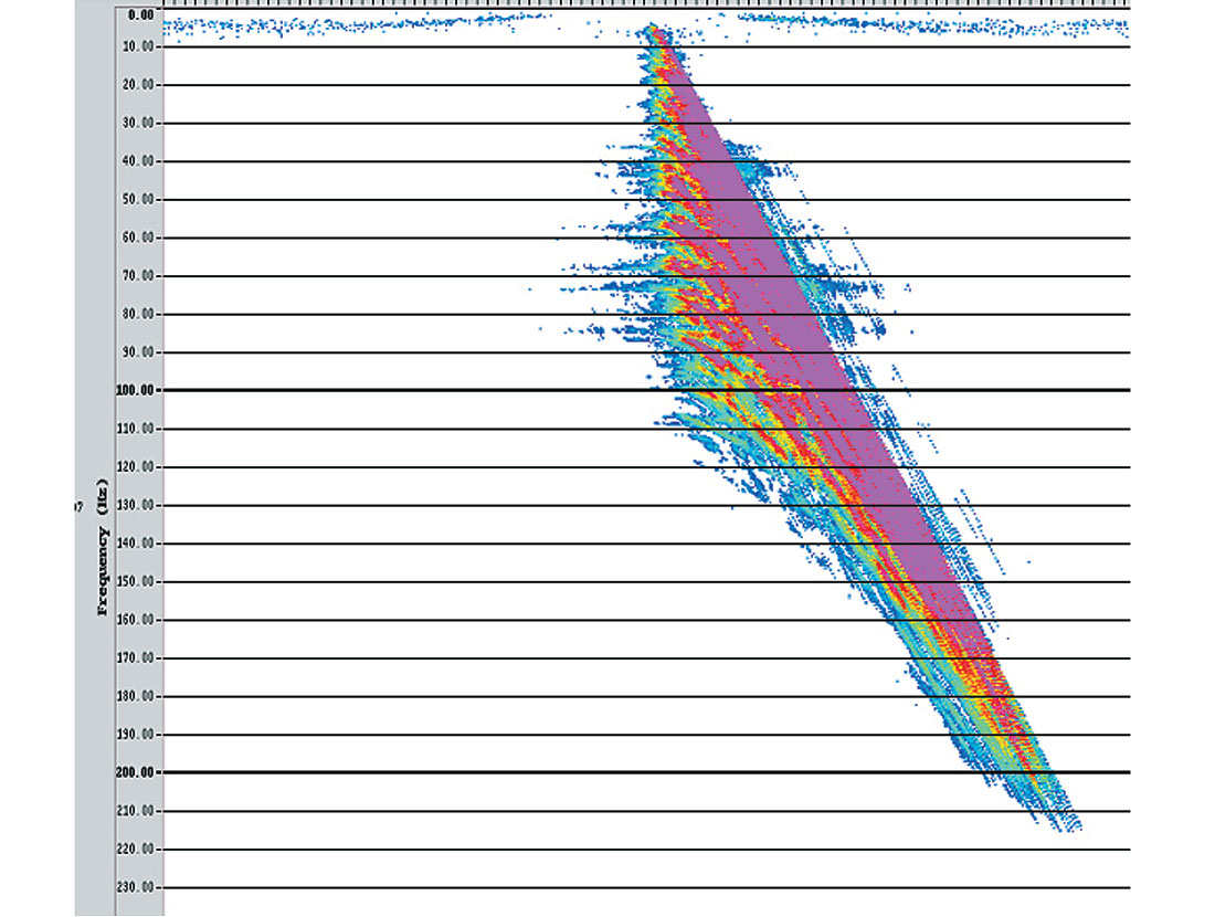
WesternGeco has developed a new seismic acquisition and processing system, Q-Marine, that is installed now on four of our vessels. The Q-Marine system sets the standard for near-future towed marine systems in terms of single-sensor acquisition, towing and steering technology, receiver positioning, and calibration of seismic measurements. I will illustrate the capabilities offered by single-sensor acquisition for coherent noise attenuation. If the coherent noise is properly sampled in the shot domain, digital group forming can be done in processing to successfully attenuate the noise. In Figure 8, we show a raw single-sensor shot gather with a 3.125-m group interval that was recorded without the lowcut system recording filter. We can see that the low frequencies and high-amplitude swell noise masked the seismic events. After a 2-Hz low-cut filter and a linear adaptive coherent noise attenuation algorithm are applied, the swell noise is attenuated (Figure 9). Figure 10 shows an example of a single-sensor shot gather recorded in shallow water. The guided waves at far offset masked the seismic signal that we would like to recover for AVO processing. Figure 11 shows the FK spectra of the same record, and it can be noticed that the guided waves are not aliased. Single-sensor recording gives us the possibility to process the data at the spatial sampling rate that preserves the higher frequencies without aliasing effects.
We consider that future developments will continue to focus on advanced spread control that will allow deployment of a large number of long streamers with closer streamer separation and source steering. This will make it possible to acquire seismic data with better sampling for 3D multiple attenuation techniques, a wider azimuth for imaging, improved acquisition repeatability for 4D seismic data, and also to do better data regularization in processing. Equally important for the seismic wavefield sampling is the source sampling. Multisource acquisition improves the sampling in the y direction but decreases the sampling in the x direction ( sail-direction). Simultaneous source shooting using encoding techniques has been developed to address this problem. The use of multiple source vessels and simultaneous shooting could make possible full azimuth acquisition with towed streamers (Sukup, 2002).
We can foresee a new generation of 4C-ocean bottom systems for shallow and deep water exploration with improved coupling and vector fidelity recording, improved positioning capabilities and cost-effective operations. Recording of the particle velocity vector and the pressure enable us to decompose the data into down and upgoing P– and S-waves, and to derive elastic rock properties. With stationary receivers, a dense sampling can be implemented in common receiver gathers using a source vessel with multiple source arrays. To implement 3D symmetric sampling, – the ideal way to sample the seismic wavefield (Vermeer, 2002) –, the R&E effort has to focus on the receiver side: reduced cost per unit, reliability, fast deployment and retrieval.
Conventional survey design is based on the assumption of horizontally layered earth model and midpoint analysis. The trend is to use subsurface earth model and common reflection point analysis for survey design and acquisition geometry analysis. 3D ray tracing and full wave equation simulation methods will be more and more used in survey design (Jurick, 2003). Based on onboard real-time target illumination studies and streamer steering capabilities, marine acquisition could be optimized for infill and undershoot operations as well as complex target illumination (Moldoveanu, 2003). Another trend in survey design is to optimize the acquisition geometry for data processing : multiple prediction and subtraction, angle dependent amplitude analysis and prestack imaging (Veldhuizen , 2004).
– Nick Moldoveanu
Question 4
Feathering of streamers has been a real problem in the acquisition of marine seismic data. This would create artifacts in time lapse seismic where repeatability is a key issue. How has this problem been addressed lately?
Answer 1
There are basically three ways to address the problem of poor repeatability caused by streamer feathering; large overlaps between adjacent swaths, steerable streamers or permanent receivers on the seafloor.
Cable feathering in conventional streamer data causes variable receiver positions, and together with additional variations in source positions when data are shot for coverage, this is probably the most fundamental limitation to improved 4D repeatability. Because marine seismic data are under-sampled in the cross-line direction, this cannot be fully compensated for during processing.
There has been a growing appreciation that it may be worth extra expenditures to acquire data more carefully for 4D purposes. Fairly straightforward improvements are denser cable separation and overlapping swaths, with source positions on parallel pre-defined lines. Denser spatial sampling reduces the alias errors and the position variations within a bin-gather. Overlapping swaths gives less variable coverage at the swath boundaries, and makes a moderate degree of cross-currents and feathering acceptable. However, to completely eliminate the feather effect, the required spacing between boat lines would increase the acquisition effort dramatically.
New streamer technology, called Q marine, provides horizontal streamer steering, and this ability can be used to improve repeatability from survey to survey. In tests we have seen an improvement in repeatability compared to conventional acquisition, as expected. Our experience from a number of surveys in Norwegian waters is that streamer steering is stable, accurate and robust, and little extra seismic noise is added by active steering. The current limitation is about 3 degrees steering against natural feather. To obtain a full zero-feather survey, infill would usually have to be shot, or one would have to increase the maximum steering force further. A major advantage of the system is the ability to get high-quality data coverage closer to surface obstructions. With an additional shooting vessel, low-azimuth undershoot data can acquired.
Permanently installed seafloor sensors will eliminate spatial variations on the receiver side. Front-end investments in hardware and deployment will be high for such systems, and little real-data experience exists. In order to limit costs, coarser receiver sampling than along a towed streamer is a solution, but this will give more aliased source-generated noise, unless the shot sampling is very dense. Variable source positions and source output will remain the same cause of non-repeatability as for towed streamer data. More experience on quality, cost and reliability of permanent seafloor receivers is needed to assess the value of such systems.
For the time being I would say that steerable streamers (Q Marine) offer a good alternative, but not the only one, for improved repeatability. And better quality opens opportunities for high-precision monitoring of tight reservoirs and over shorter time-periods than has been common up to now.
– Ola Eiken
Answer 2
Many time-lapse (4D) marine seismic projects have been reported as successful. These are usually characterized by large changes in reflection strength, where acoustic impedance contrast has a high sensitivity to change in fluid saturation (and/or pressure) and there has been sufficient elapsed production time to give rise to such a change. Not all 4D projects are as dramatic as those typically featuring in technical conferences. The 4D signal is not always strong and difference energy may appear in the seismic data that does not relate to a change in the seismic response at the reservoir. Such difference energy is often referred to as ‘4D noise’ and, depending on the strength of the 4D signal, will give rise to uncertainty in the interpretation of results. Poor 4D signal-to-noise ratio has also tended to restrict the interpretation of 4D datasets to being qualitative rather than quantitative. Furthermore, it has limited the application of the 4D seismic technique to fields above a certain threshold level of expected 4D response and with relatively long elapsed periods of hydrocarbon production. On all these counts, improving 4D signal-to-noise ratio is a vital goal for the seismic industry.
There have been several papers in recent years that have discussed how the repeatability of the acquisition system configuration can impact the repeatability of the seismic measurement and thereby the quality of time-lapse seismic results (Landrø, 1999; Eiken et al., 1999; Hartung et al., 2000; Kragh et al., 2001; Calvert et al., 2002). If data in a monitor survey are not acquired in an identical manner to that of a baseline survey then differences will be seen in the seismic data that do not relate to 4D signal. Carefully controlled, calibrated acquisition measurements are essential in order to reduce 4D noise and lower the threshold for useful 4D signal. Of all the acquisition parameters to be controlled, streamer positioning is the most intractable and for most of the marine seismic industry’s history has been completely open to the effects of ocean currents. This is usually referred to as ‘feathering’, but in fact streamers exhibit curved shapes that the familiar, simple feathering metric fails to describe. Although still in widespread use, it is anticipated that ‘feathering’ metrics will in future be superceded by ‘streamer positioning’ metrics.
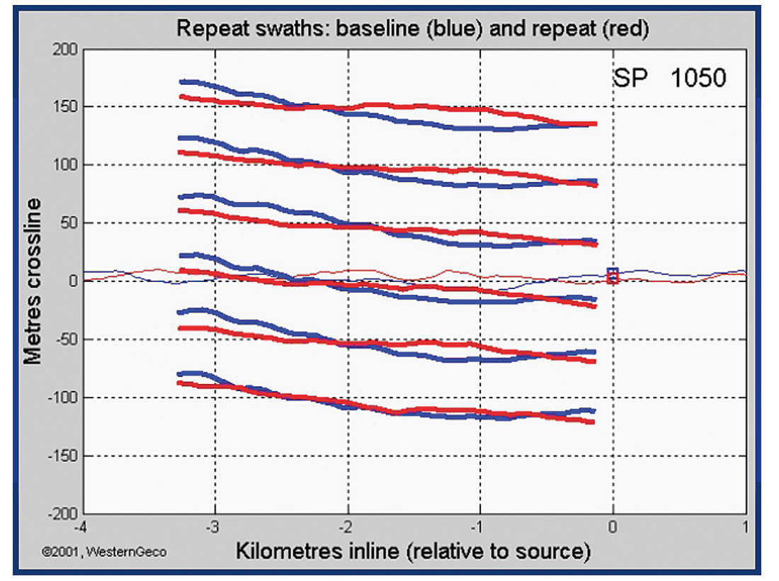
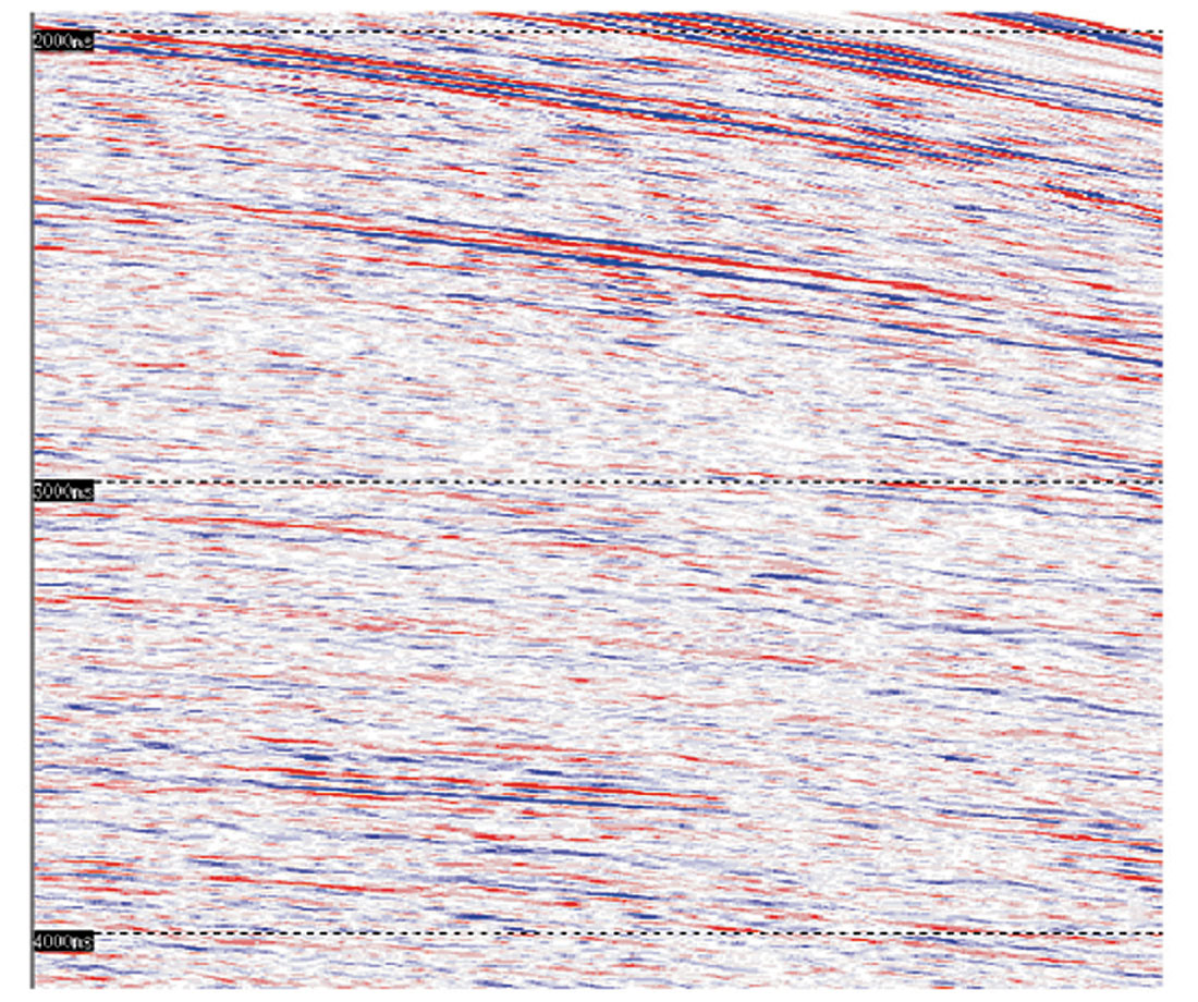
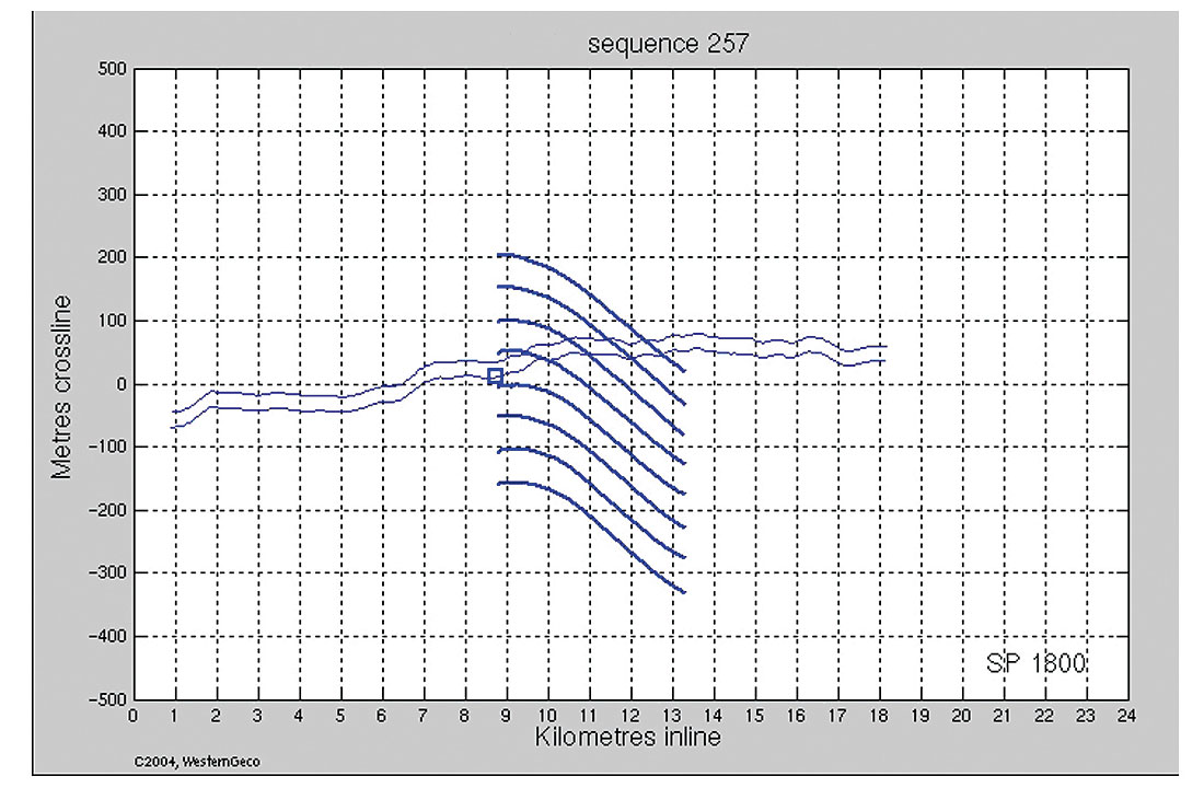
In a paper presented at the Annual SEG meeting in Salt Lake City (Curtis et al., 2002), this correspondent presented results of using a streamer steering system (Bittleston et al., 2000) to control and constrain streamer positioning of two North Sea 3D surveys intended to be the baseline for future surveys, also to be acquired using steered streamers. The 2001 survey design called for streamers to be towed with “zero feather” along pre-plot sail lines. During the course of each survey two sail line swaths were re-acquired as a test of the measurement repeatability. In these experiments, the cross line positioning difference achieved between the baseline and repeat swaths was within 10 metres for most of the line length (see figure 12). The results of processing the data using a fully deterministic sequence (i.e. no cross-equalization applied) are seen in figure 13. At that time, these repeatability comparison tests could only demonstrate a lack of 4D noise in the difference sections; a ‘blank’ canvas on which to paint a 4D response. The elapsed time between the repeat swath experiments was only a matter of days, with no material change due to production and therefore no measurable 4D signal. However, in 2003, a monitor survey was acquired over one of the two reservoirs, after 22 months of elapsed production time.
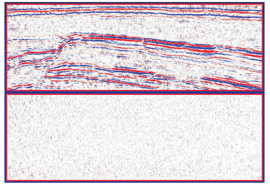
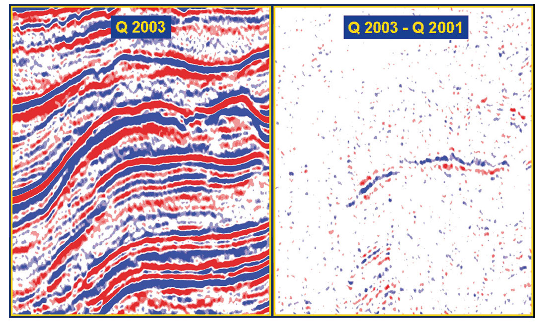
Figure 14 shows the difference between streamer positions for every sail line in the baseline and monitor survey, described here in the familiar terms of feathering. The predominance of blue in the display represents close to zero difference in streamer position between the two surveys. Warm colors along the centre line of the survey are due to the presence of an FPSO, where priority has been given to steering streamers as close as possible to the obstruction in order to minimize the requirement for undershooting. An example section from one of the 3D volumes and the corresponding section from the 4D difference volume are shown in figure 15. In this figure, a distinct 4D response can be seen that corresponds to anticipated effects of injection and movement of the fluid contact. 4D events seen near the bottom of the display window are interpreted as the effect of travel time changes induced by localized reservoir pressure change between surveys. However, the key observation of those readers familiar with 4D seismic data will most likely be the very low level of background 4D noise energy in this figure. Confidence in the good 4D signal-to-noise ratio of these data was high enough for the fast-track 4D volume created on-board (enabled by the deterministic processing workflow) to be used for re-positioning a planned horizontal well track when interpretation of those data indicated a risk of early water breakthrough.
Streamer control in this system is achieved by the use of ‘bird-like’ steering devices, called Q-Fins, which have independently controlled wings. Highly accurate receiver locations, from a full-spread acoustic network streamer positioning system, are used within a feedback loop where the desired spread configuration is compared to the actual positions. Adjustments are made by rotating the wing angles of the Q-Fins to achieve combined depth control and lateral positioning control. Q-Fins are distributed regularly along each streamer. In 2003 surveys, the density of Q-Fins was increased in order to increase the potential steering forces that could be applied to the streamer. This improved the ability to repeat the 2001 baseline survey positioning. In the limit, a Q-Fin can be placed between every streamer section. Recent tests have been conducted with a variety of configurations to investigate the bounds of the system capability. Similar tests conducted with the 2001 configuration demonstrated the ability, at that time, to steer streamers up to +/-3 degrees from natural feather angles. Steering streamers against the current creates cross-flow turbulence which results in vibration and so-called ‘streamer noise’.
Tests of the 2001 configuration demonstrated that this noise mechanism, which is identical to that induced by the crossflow associated with wave action, is relatively weak (compared to typical weather-induced noise) and that the noise attenuation achieved by digital filters applied to the well-sampled coherent noise recorded by the Q-Marine single sensor acquisition system is highly effective.
Currents in the North Sea, which are primarily associated with tide cycles, can be predicted with sufficient accuracy to enable lines to be acquired at times where the capabilities of streamer steering are optimally effective. Production statistics have shown that careful forward planning can minimize potential lost time, and savings in the acquisition of ‘infill’ more than compensates for any wait time. The required accuracy for repeat positioning may vary from region to region. In the area of the North Sea for which figure 15 is an example, there are near surface irregularities that are the source of diffraction and diffracted multiple noise. Close repetition of source and receiver positions are necessary if noise characteristics are to be repeated and therefore removed from the 4D result. Simply repeating sub-surface or ‘CMP’ positions is not considered good enough unless also associated with repeated offset and azimuth (i.e. repeated source and receiver position).

Strategies for acquiring repeatable surveys in different oceans, where currents are less predictable or stronger than those typically observed in the North Sea, are continually evolving. Analysis of many years of survey statistics shows that about 75% of all marine shot records are acquired with feather angles less than 6 degrees, which is potentially within the control range of steered streamers. In those cases where currents cannot be so controlled, steered streamers can deliver moderated feathering, consistent separation along the entire streamer length and safe control of closely spaced streamers (see figure 16). These features, together with repeatability analysis performed within the navigation system, can provide efficiencies in the acquisition of time-lapse surveys performed under difficult ambient conditions.
Acknowledgements: I would like to acknowledge Statoil and partners for permission to show the seismic data displayed in this response.
– Tony Curtis


Share This Column