Introduction
A primary goal of microseismic surveys is to locate the origination point of seismic events that occur in response to hydraulic fracture stimulation in a reservoir. Accurately locating the origin point of seismic events relies upon a complete understanding of wavefield propagation phenomena that occur in the environment of the reservoir treatment zone. For many economically important geologic formations the seismic velocity field is highly variable in a vertical direction in the neighborhood of the treatment formation. Often the treatment formation has a significantly lower velocity than rock formations above and/or below the treatment zone. Large vertical velocity variations engender refractions, converted modes, and trapped energy, all of which add complexity to the seismic wavefield that is recorded in observation wells.
The purpose of this paper is to discuss implications for accuracy and uniqueness of seismic event locations in light of wavefield phenomena involving refracted first arrivals, trapped modes, and mode conversions. The principal conclusions of this study are related to the design of seismic receiver placement in microseismic surveys so that the recorded data will allow unique event positions to be determined and so that data processors can know the limits of the data to provide unique event positions. Implicit in this conclusion is that seismic data acquisition planning is as important for microseismic applications as it is for surface seismic and for the same reasons. The data acquisition plan must anticipate how the seismic wavefield will interact with the seismic velocity field and seismic receivers must be placed in a location that will capture a useful part of the wavefield from all anticipated source locations.
Fundamental Seismic Wave Phenomena and Microseismic Data
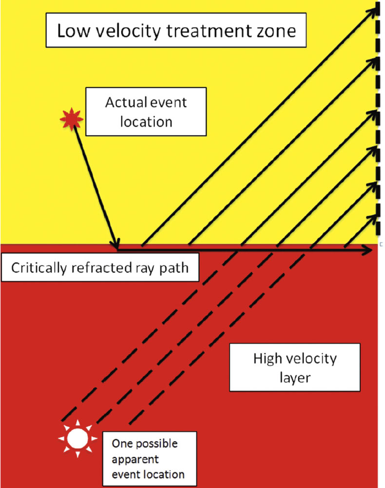
Seismic wavefield phenomena such as critical head wave refraction, converted waves, trapped modes, and seismic anisotropy have been understood both mathematically and observationally by physicists and seismologists for many decades. Additionally, each of these phenomena has been observed to affect the recorded seismic wavefield in microseismic surveys in ways that, if ignored, can lead to incorrect determination of seismic event locations and significant economic repercussions. Figure 1 for example shows a 2-layer case in which the upper layer has a P-wave velocity of 4,250 m/s and the lower layer has a much higher P-wave velocity of 6,800 m/s. The scenario shown in Figure 1 is modeled largely on the Barnett/Viola or Barnett/Ellenburger interface in which the economically important Barnett formation is the shallower lowervelocity layer. In Figure 1 the P-wave first arrivals from a seismic event that originated in the treatment zone (upper layer) have arrived at the geophones by way of a critically refracted headwave that has traveled through the high-velocity (lower) layer. In Figure 1 the P-wave first arrivals encountered the geophones after having escaped the higher-velocity layer at the critical angle between the two layers. Particle motion analysis of the P-wave would lead to an event location (seismic image point) that projects from the geophones back along the upgoing ray path and may erroneously place the event in the deeper high-velocity zone which may lead to an unnecessary early shutdown of frac pumping and ultimately reduce production from the formation.
Wavefield Modeling for Survey Design
Seismic wavefield modeling, such as the finite difference method, allows simulation of the interaction between the velocity field and the seismic wavefield generated by fracture events. Seismic modeling results can provide an objective means by which to design seismic receiver placement, vertical receiver aperture, and receiver density in observation wells. The goal of modeling is to design receiver placement such that seismic receivers will always record a useful part of the seismic wavefield for all likely locations of seismic events. Further, modeling provides a means of predicting which seismic receivers should not be used for locating events from specific regions relative to observation wells because they may have recorded waveforms that cannot contribute to a unique event location and may actually provide incorrect results.
Figure 2 shows a wavefield snapshot from a finite difference seismic model. The vertical axis of the plot is depth and the horizontal axis is distance from the edge of the model. The velocity field for the model was based on the Barnett Formation with the lower-velocity Barnett above higher velocity carbonate (Viola Formation). A vertical black line indicates the location of a seismic receiver well that is offset 350 m horizontally from the hypocenter of a microseismic event in the Barnett Formation. The model shows that the first arrivals seen by geophones at the depth of the Barnett Formation are critically refracted head waves that have arrived at the receiver well via refraction along the top of the Viola. Critically refracted head waves cannot in general be used to uniquely locate seismic events. The model also shows that geophones that are significantly above the Barnett will record direct body waves from the fracture event location which are needed for accurate fracture event location mapping.
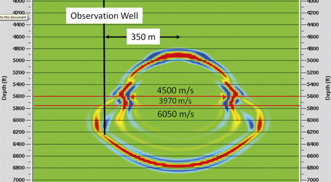
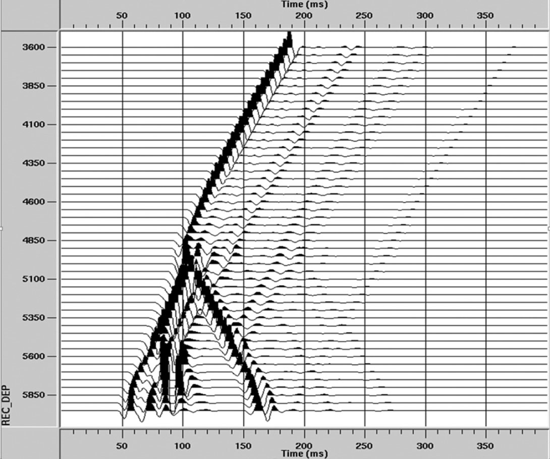
Figure 3 is the seismogram that was produced from the finite difference model shown in Figure 2. As noted above the first arrivals recorded by deeper geophones are critically refracted head waves. These waveforms are followed by higher-amplitude events that arrive as trapped modes in the low velocity zone. A data processor would use a model result like this to conclude that the deeper geophones are not suitable to accurately locate this seismic event because the seismic signal recorded on the deeper geophones is contaminated by critically refracted head waves and trapped modes. The shallower geophones however receive direct body waves that have not traveled via critical refraction and can be used to locate seismic events. Note that the deep geophones would have been quite useful in locating a seismic event that originated near the observation well but the shallow geophones might not have been as useful for that event. Thus the placement of seismic receivers for microseismic monitoring should be a function of how the seismic wavefield is expected to interact with the seismic velocity field and how far the seismic events are likely to be from the observation wells. Economically important formations besides the Barnett Formation are subject to wavefield phenomena as described above. Other examples are the Marcellus Shale and the Eagle Ford Shale.
Conclusions
Seismic data acquisition planning is as important for microseismic applications as it is for surface seismic and for the same reasons. The data acquisition plan must anticipate how the seismic wavefield will interact with the seismic velocity field. Seismic receivers must be placed such they that will capture a useful part of the wavefield at all locations from which microseismic events are likely to originate. Seismic modeling provides ways to evaluate optimal data acquisition plans. The examples shown are based on the Barnett shale gas formation where there is a high vertical velocity gradient near the depth range of the treatment formation but the lessons are equally important for any location.


Join the Conversation
Interested in starting, or contributing to a conversation about an article or issue of the RECORDER? Join our CSEG LinkedIn Group.
Share This Article