What is Rock Physics?
Rock Physics describes a reservoir rock by physical properties such as porosity, rigidity, compressibility; properties that will affect how seismic waves physically travel through the rocks. The Rock Physicist seeks to establish relations between these material properties and the observed seismic response, and to develop a predictive theory so that these properties may be detected seismically.
Establishing relationships between seismic expression and physical rock properties therefore requires 1) knowledge about the elastic properties of the pore fluid and rock frame, and 2) models for rock-fluid interactions. This is the domain of Rock Physics.
Rock Physics / Petrophysics: What’s the difference?
Stated very simply, (and therefore with apologies to Rock Physicists and to Petrophysicists):
| Rock Physics... | Petrophysics... |
|---|---|
| Rock Physics uses sonic logs, density logs, and also dipole (shear velocity) logs if available. | Petrophysics uses all kinds of logs, core data and production data; and integrates all pertinent information. |
| Rock Physics aims to establish P-wave velocity (Vp), S-wave velocity (Vs), density, and their relationships to elastic moduli κ (bulk modulus) and μ (rigidity Modulus), porosity, pore fluid, temperature, pressure, etc. for given lithologies and fluid types. | Petrophysics aims at obtaining the physical properties such as porosity, saturation and permeability, which are related to production parameters. |
| Rock Physics talks about velocities and elastic parameters, because these are what link physical rock properties to seismic expressions. | Petrophysics is generally less concerned with seismic, and more concerned with using wellbore measurements to contribute to reservoir description. |
| Rock Physics may use information provided by the Petrophysicist, such as shale volume, saturation levels, and porosity in establishing relations between rock properties or in performing fluid substitution analyses. | Petrophysics can provide things like porosity, saturation, permeability, net pay, fluid contacts, shale volume, and reservoir zonation. |
| Rock Physics is the interest of Geophysicists (and maybe Physicists). | Petrophysics is the interest of Petroleum Engineers, Well Log Analysts, Core Analysts, Geologists and Geophysicists. |
Why do we need Rock Physics?
Accurate relations between rock properties and seismic attributes can to put “flesh on the bones” of a seismic interpretation. That is, Rock Physics allows the interpreter to put “rock properties together with seismic horizons.” (Peeters). Information about porosity, pore-fill, and lithology becomes available to augment the seismic interpretation.
What can Rock Physics studies contribute?
Typical Rock Physics studies will answer questions such as:
- can porosity and saturation be obtained from (seismic) interval velocity?
- what are the velocity-porosity relations in various lithologies?
- is seismic AVO response sensitive to gas saturation levels in a particular play?
- how sensitive?
- what increments of gas saturation can be detected seismically?
- how robust would AVO seismic response be in situations of varying thickness?
- how robust would AVO seismic response be in situations of varying porosity?
- can an optimal processing strategy be determined for processing the seismic data for AVO analysis?
- what seismic characteristics or attributes may be useful to distinguish gas-sand from shale?
- what is the influence of gas saturation on velocities, density and reflectivity in a particular play?
- what is the influence of clay content?
- what is an appropriate mudrock line value for further AVO analysis of a particular play?
Establishing relationships between seismic expression and physical rock properties therefore requires 1) knowledge about the elastic properties of the pore fluid and rock frame, and 2) models for rock-fluid interactions. This is the domain of Rock Physics.
Rock Physics in Practice: some examples
Example 1: Cross-plotting well log data
A typical task in a Rock Physics study is to calculate AVO attributes from the well logs and cross-plot various attributes from selected geologic units. These cross-plots are used to:
- understand how the rock properties are related
- determine the resolution of rock properties in various lithologies in the area
- determine the sensitivity of various attributes to fluid effects
- contribute velocity constraints such as mudrock line values to AVO analysis of seismic data.
- contribute to interpretation of attribute sections: which attribute(s) are best for describing a given reservoir?
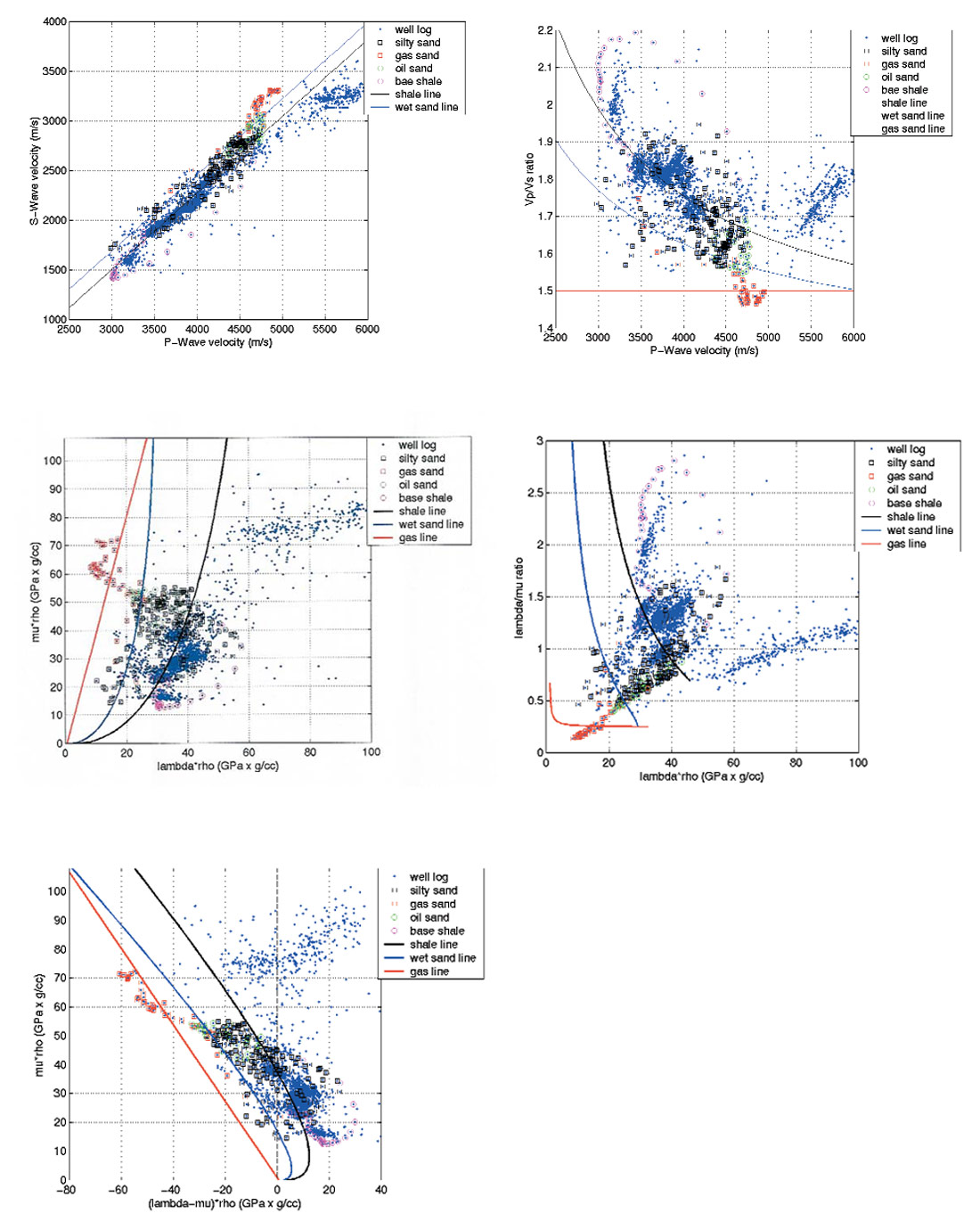
The following example is from a well log from western Canada. Data points from various depth intervals are cross-plotted in various attribute spaces. Note how data from various depth intervals (lithologies) cluster. Note also how the clusters are separated more easily in some attribute spaces than in others.
 nds in a particular play.
Example 2: Crossplotting seismic data
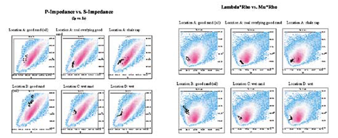
This example illustrates how crossplots can be used to see which attributes may show clear separation for the zone of interest. In this case, the zone of interest is an oil-bearing sand.
On the following page are crossplots from AVO Attribute sections derived from pre-stack seismic data. The highlighted data points are taken from data at well locations A, B, C, and D, over the zone of interest (as interpreted on the AVO Attribute time sections). Note differences in separation of clusters in the Ip versus Is (P-Impedance versus S-Impedance) crossplots as compared to the Lambda*Rho versus Mu*Rho crossplots. This set of crossplots illustrates how, at least in this study area, good sand may be distinguished from coal, shale, wet sand, and regional wet sand by crossplotting AVO attributes or elastic rock properties, and that various attributes are available for crossplotting.
One could then use this knowledge of crossplot cluster patterns at known wells to further investigate cluster patterns at various other well locations, and at potential locations beyond.
Example 3: S- wave velocity prediction
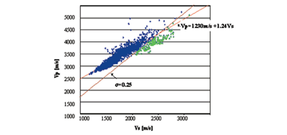
Shear wave velocities are required for most AVO analyses. However, the S-wave velocities are not commonly logged, and often must be predicted from P-wave sonic logs. This is another typical task of the Rock Physics study.
In this example from northern Mexico, the P-wave velocity model was built by calibrating the interval velocities obtained from NMO analysis of the seismic data with the sonic velocities. The mud-rock line, estimated from the well’s P- and S- velocities, and shown in the figure below, was used to scale and shift the P-wave velocities to obtain the S-wave velocity field.
Example 4: Fluid substitutions
Another practical application of Rock Physics is to perform fluid substitutions in well log data, to assess ‘what if’ possibilities. For example, the gas-charged zone of a well log can be edited to simulate the wet well case. Fluid substitutions should not be considered to be trivial matters because fluid type plays an influence on many properties. For instance, one cannot simply lower the P-velocity to substitute gas for brine, the density will also be affected when gas is substituted for brine. The main point here is that fluid substitution studies cannot be approached casually.
In addition to fluid substitutions, sensitivity to thickness of a rock layer may be examined by perturbing the well logs to alter the thickness, or even to remove the layer. Attributes can be calculated from the modified wells to simulate seismic response to the various thickness increments.

Similarly, porosity, saturation, or other physical properties could be incrementally changed by editing the logs, then calculate Vp, Vs, density, and elastic moduli relationships to investigate seismic response. This is illustrated in the next example.
Example 5: 1.5D pre-stack seismic modeling
Reservoir rocks have physical material properties. Pre-stack seismic modeling means calculating the synthetic pre-stack seismic gather that would result from these rock properties. Pre-stack seismic modeling essentially presents similar information as does cross-plotting, but since synthetic seismic wiggle traces are output, one has the added benefit of being able to view seismic expression for the modeled earth properties, not just well logs or crossplots.
Synthetic seismic gathers are generated by calculating how the wavefield would pass through an earth model. The earth model is first constructed by using sonic, density, and shear wave logs to form a description of the subsurface depth.
There are two main modeling algorithms: Zoeppritz and Elastic wave equation. The Zoeppritz equations modeling uses ray tracing and approximates the source signal as a plane wave propagating through our earth model. The more computationally intensive Elastic Wave Equation modeling provides a more sophisticated result by using the full wave equation to propagate the spherical wavefront through the depth model. It accounts for peg-leg multiples, surface multiples, absorption, transmission losses, and converted waves.
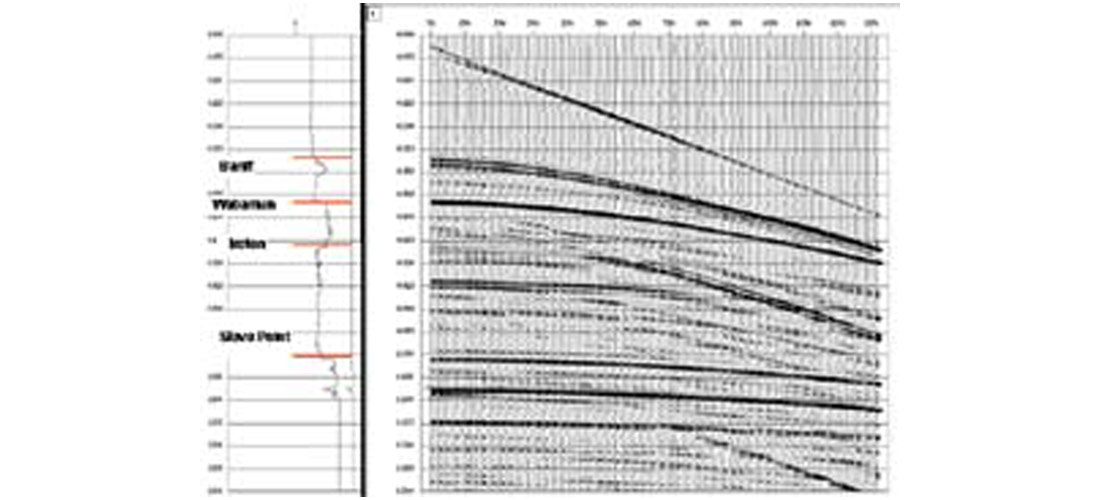
The synthetic pre-stack gather can then be processed in the same way as one would process any real pre-stack gathers. This includes extracting AVO attributes and Lame’s parameters from modeled synthetic gathers in just the same way as one extracts these from real pre-stack data. In this way one can predict from the model those attributes, if any, which will be useful AVO hydrocarbon indicators for actual seismic data.
As mentioned earlier, one can vary reservoir properties such as the fluid type, porosity, thickness, to study the resulting seismic AVO response and investigate possible non-unique physical causes of the observed seismic response. We can also study the sensitivity of the seismic to acquisition parameters, signal to noise ratio, bandwidth, and processing parameters.
Example 6: 2D pre-stack modeling
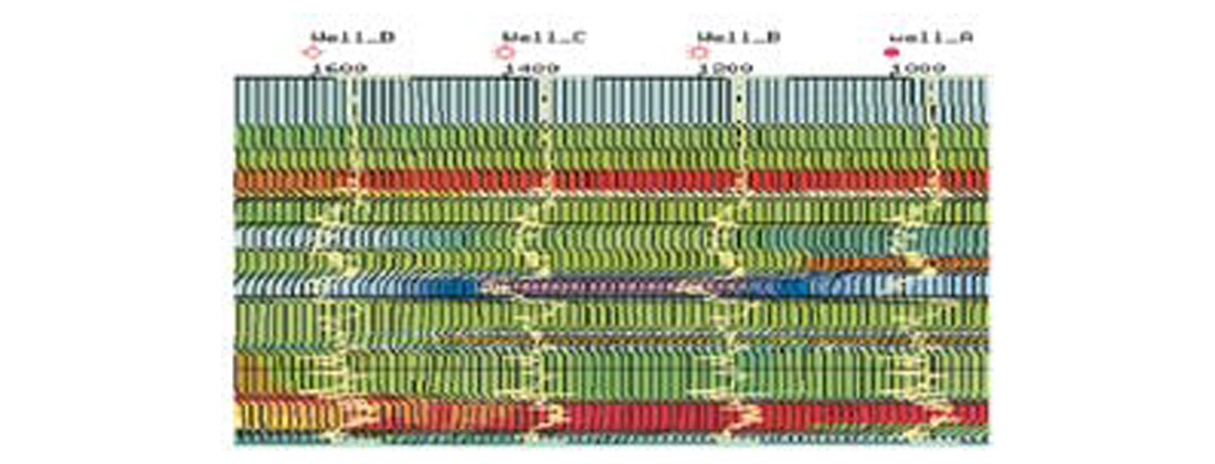
Using horizon based interpolation, several well logs can be used to construct a 2D geologic earth model and generate an interpolated ‘2D Line’ of synthetic pre-stack gathers. One can stack this ‘line’ of modeled pre-stack gathers to study the stack response. One can also extract pre-stack AVO attributes and assess the relative importance of attributes before investing time and effort in an AVO analysis of actual field seismic data.
Digging Deeper: Where does all this come from?
Two approaches: Theoretical and Empirical
Equations that attempt to describe the relationships between seismic velocities and lithology, porosity, pore fluid, etc. are either theoretical or empirical. Theoretical relationships start with underlying physical principles and attempt to propose a universal relationship (at least for the assumptions they may be forced to make). One of the amazing things about many theoretical relationships in Physics is how well they can work. But they all break down at some point or in some particular circumstances when assumptions, sometimes hidden, are violated.
Empirical relationships are derived from experiment. Physical properties of a suite of rock samples are measured, analysed, graphed, and a mathematical function (often a linear equation of the form y = mx + b) is fit to the data points. Sometimes a linear fit is natural (the data points are linear for the most part, but in some manner fall away from a linear trend, often near the end points). Sometimes measured data points fit to nonlinear equations. Empirical relations most often work very well for the data they were derived from, but can be difficult to compare from one research project to the next. With empirical relations one must be careful about ascribing physical meaning to what are essentially generic mathematical formulae.
Zhijing Wang summarizes the tension between theoretical and empirical approaches this way:
Most direct measurements are carried out either in the laboratory or inside a borehole, whereas most theoretical calculations are based on the Gassmann equation (Gassmann, 1951) because of its simplicity and ease of use. Direct laboratory measurements are carried out uncontrolled, simulated reservoir environments and provide accurate effects of pore fluids on seismic properties. Direct borehole measurements, however, are often affected by uncontrollable factors such as stress concentration, hole washout, mud invasion/ filtration, and saturation conditions. In both laboratory and borehole measurements, the wave frequencies are higher than seismic frequencies.
Theoretical calculations such as those using the Gassmann equation require input parameters that have to be directly measured in the laboratory. In fact, some theories require input parameters that are often hard to obtain with a reasonable precision. On the other hand, some theories, particularly the Gassmann equation, are based on frequencies comparable to seismic wave frequencies. Therefore, a direct comparison of laboratory results with theoretical calculations often involves the dispersion problem, where dispersion means that seismic velocities are functions of the wave frequency. (Wang, 2000, p 8)
The crux of all this is that there are a great number of relationships between seismic velocities (and constituent elastic properties) and rock parameters that are all valid to some degree but not valid always, and many that do not illuminate the physical principles involved. The trick is to try to gain a fundamental understanding so that, on a practical basis, the different relationships can be evaluated for their applicability to solving specific problems.
Gassman equations: an overview
Gassman’s (1951) equations provide a way to calculate the bulk modulus of a fluid-saturated porous medium using the known bulk moduli of the solid matrix, of the frame, and of the pore fluid. For a rock, the solid matrix consists of the rock-forming minerals, the frame refers to the rock sample with empty pores (dry rock), and the pore fluid can be a gas, oil, water, or a mixture. The equations also express that the shear modulus is not affected by fluid saturation.
Assumptions in Gassman’s equations
“The rock-fluid system is so complicated that virtually all the theories for such a system have to make major assumptions to simplify the mathematics. “ (Wang 2000, pp 9,10)
So what can be said about the uses and limitations of Gassmann’s equation?
The Gassmann equation works reasonably well for rocks with interconnected high aspect-ratio pores such as unconsolidated clean sands and sandstones at high effective pressures. (“works reasonably well” means little difference exists between the Gassmann-calculated and laboratory-measured seismic velocities).
Carbonate rocks have strong elastic frames and very different pore systems compared to siliciclastic rocks. Because many pores in carbonate rocks are not well connected, the Gassmann equation is in general inadequate for carbonate rocks.
For rocks with flat pores, cracks, or fractures, and rocks saturated with high-viscosity fluids, Assumption 5 cannot be satisfied, so the Gassmann-calculated Vp is always less than the measured Vp. This is because such pore shapes do not allow room for the fluid to equilibriate in the half-wavelength time period required by the equation.
At high pressures, the flat pores, cracks, or fractures are closed, so then the Gassmann-calculated velocities agree better with the measured values.
In unconsolidated or poorly consolidated sands, the measured shear modulus of the dry frame usually has high uncertainty because of high shear wave attenuation. A 10% uncertainty in dry frame shear modulus yields a 2% uncertainty in the Gassmann-calculated Vp.
| The basic assumptions in the Gassmann equation. (The devil is in the details) | What does this mean? |
|---|---|
| 1. The rock (both the matrix and the frame) is macroscopically homogeneous and isotropic. | This common assumption ensures that the wavelength is long compared to the grain and pore sizes. Most rock can generally meet this assumption for seismic (20-200 Hz) to laboratory frequencies (100 kHz - 1 MHz). |
| 2. All the pores are interconnected or communicating. | This implies that porosity and permeability are high. The reason behind this assumption is to ensure full equilibrium of the pore fluid flow induced by the passing wave can be attained within the time frame of half a wave period. For seismic waves, only unconsolidated sands can approximately meet this assumption because of the finite wavelength. |
| 3. The pores are filled with a frictionless fluid (liquid, gas, or mixture) | The viscosity of the saturating fluid is zero. The purpose of this assumption again is to ensure full equilibrium of the pore fluid flow. In reality, because all fluids have finite viscosities and all waves have finite wavelengths, most calculations using the Gassmann equation will violate this assumption. |
| 4. The rock-fluid system under study is closed (undrained). | For a lab rock sample, this means that the rock-fluid system is sealed so that no fluid can flow in or out of the rock’s surface. For a reservoir rock, the volume v which is under study must be part of a much larger volume V, and be located far enough from the surface of V that the passing seismic wave does not cause any appreciable flow through the surface of v. |
| 5. When the rock is excited by a wave, the relative motion between the fluid and the solid rock is negligibly small compared to the motion of the whole saturated rock itself. | This key assumption is the essence of the Gassmann equation. It requires that wavelength be infinity (or the frequency be zero). It is also perhaps the reason why the measured bulk modulus or velocity are usually higher than those calculated by the Gassmann equation. This is because at high frequencies, relative motion between the solid matrix and pore fluid will occur so that 6the waves are dispersive. |
| 6. The pore fluid does not interact with the solid in a way that would soften or harden the frame. | In reality, the pore fluid will interact with the rock’s solid matrix to change the surface energy. When a rock is saturated by a fluid, the fluid may either soften or harden the matrix. |
Biot
Gassman’s equations are not adequate to calculate frame moduli in the high frequency range of laboratory data. Biot’s (1956) theory includes the entire frequency range up to the point where the grain scattering becomes important and the rocks can no longer be considered homogeneous. Gassmann’s equations are the low frequency limit of Biot’s more general relationships. Note that for the case of perfect coupling, Biot’s equations reduce to the zero-frequency case (Gassmann’s Assumption #5 is met).
Further Refinements
Much of the ongoing research work in Rock Physics is to approach physical reality more closely. For example, the Biot equations say that the fluid must participate in the solid’s motion by viscous friction and inertial coupling, but it is known that fluid also squirts out of pores when deformed by a passing seismic wave. Traditionally, the Biot mechanism has been treated macroscopically, and the squirt-flow mechanism at the individual pore level. Work by Dvorak and Nur (1992) offers a model which treats both mechanisms as coupled processes and relates Vp and attenuation to macroscopic parameters: the Biot poroelastic constants, porosity, permeability, fluid compressibility and viscosity, and a new microscopic- scale parameter - a fundamental and measurable characteristic squirt-flow length. Such local flow models are representative of current work to extend Gassmann’s description to include more realistic portrayals of rocks, and to relative poroelastic behavior to macroscopic measurable parameters such as permeability, porosity, saturation, pore-fluid compressibility, density, and viscosity). Please see ‘For Further Reading’ for some excellent papers in this regard.
Issues in Rock Physics
The challenge of scale
The scales at which Geophysics and Petrophysics work are very different. Logs and cores give resolution less than 0.3 metres, while seismic resolution is often no better than 15 metres. This may be expressed in terms of the frequency ranges used:
- The range of seismic frequencies is typically considered to be 20 - 200 Hz (and more realistically 10 - 80 Hz)
- Logging frequencies are around 10 kHz
- Laboratory frequencies have traditionally been 100 kHz - 1 MHz. Also note that in the lab, it has been nearly impossible to carry out wave propagation measurements at low (seismic realm) frequencies as the sample length is required to be at least half a wavelength. For a rock with 4000m/s Vp, a 50Hz wave would require a 40m sample. However, recent promising advances in Rock Mechanics have succeeded in velocity measurements in the lab at the 100Hz range, which is very promising indeed (Lewis Lacy, Director of Geomechanics, CoreLab Rock Mechanics Lab, personal communication).
The challenge of focus
Advances in computing power mean that efforts are turning from the traditional seismic task of getting an accurate image of subsurface structures to extracting more and more rock property information from the seismic wavelet. Computing power also benefits Reservoir Modeling, and as more complex dynamic simulations become possible, real integration of seismic and reservoir characterization gets closer. Establishing accurate relations between rock properties and acoustic parameters is becoming more imperative. “If the trend in computering power continues, a 3-D earth model with geological, petrophysical, and geophysical data in all grid-blocks will be available soon. This ‘unified model’ would have the resolution of cores near the well bore; of logs in most other places; and will be used for both static and dynamic modeling.” (Peeters)
The challenge of calibration
Seismic sections that show rock and fluid properties will be more meaningful if they can be calibrated with forward modeling from accurate rock properties measured at seismic frequencies. There is a huge difference between a 50 Hz seismic wavlet (approximately 40 m resolution) and a 10 kHz sonic wireline tool (20 cm). Which high frequency results can be extrapolated to the seismic realm?
The lack of measured shear velocities
Dipole logs are not commonly performed, and estimates of Vs carry uncertainty, particularly in unconsolidated sediments.
The promise of the prize
Just a few of the problems facing the geoscientist are mentioned above. There are plenty of issues and shortcomings with Rock Physics, as with any discipline handling complex physical processes. Nonetheless, the Rock Physics effort is progressing in a valid direction. The achievement of rock properties from seismic data, integrated with wireline, petrophysical, and geologic knowledge is a goal that is becoming more attainable. Rock physics draws together the disciplines of Geophysics and Petrophysics, bringing the possibility of a unified 3-dimensional earth model within reach.

Acknowledgements
I am indebted to my colleagues Yongyi Li, Alvaro Chaveste, and Michael Burianyk for their assistance.


Join the Conversation
Interested in starting, or contributing to a conversation about an article or issue of the RECORDER? Join our CSEG LinkedIn Group.
Share This Article