Within the vicinity of Saskatoon, Saskatchewan, potash is conventionally mined by three operating companies at five different mines. Continuous boring machines (borers) cut the potash out of the seams at about one kilometer depth.
The stratigraphy of the roof above the mined-out rooms (salt-beam) in the Saskatoon area mines consists of a series of salt beds separated by well-known and regionally distributed planar clay seams. When geological disturbances or anomalies are encountered during mining, conditions can become hazardous to personnel and equipment due to failure in the roof, which can cause significant volumes of rock to fall. These incidents are known as unplanned falls-of-ground. Mining crews are well-trained in the mining procedures and how to identify hazardous conditions, but occasionally subtle geological anomalies can be difficult to identify. Such scenarios are concerning because a combination of subtle geological anomalies can create conditions for falls-of-ground that occur with little to no warning.
There is no silver-bullet solution to prevent unplanned falls-of-ground. Typically, such events occur due to a combination of seemingly remote factors aligning – the classic “Swiss Cheese model”. In this paper, we describe the development of a standardized suite of mining practices at three Saskatoon area mine sites operated by Potash Corporation of Saskatchewan Inc. (PotashCorp). Geoscientists played a major role in the development of these standards because it was recognized how important it was that the crews had a working knowledge of the geology at their jobsites. Education of crews was vital in this effort and the ground control standards were used as a foundation for the updated training materials. To help the miners better understand the geology above them, in the mined-out rooms, geophysicists worked with engineers to develop a borer mounted ground penetrating radar (GPR) package. Its purpose is to provide real-time mapping of roof stratigraphy to help to determine if conditions, which might lead to instability, are present in the mine roof. This development is the first known successful trial of real-time, continuous upward looking GPR on potash boring machines and it offers the potential of increasing mining safety.
Introduction
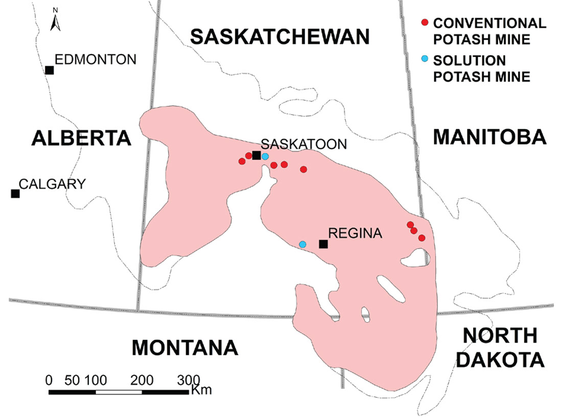
Conventional underground potash mining in Saskatchewan occurs within a comparatively narrow, 500 km long corridor running from the Saskatoon area to the southern border with Manitoba (Figure 1). This corridor roughly parallels the shallow northern sub-crop edge of the Prairie Evaporite salts which host potash deposits at depths of 925 to 1200m. Currently there are eight mines in Saskatchewan where potash is mined using conventional underground mining techniques, and there are three solution mines. Within about a 100 km radius of Saskatoon there are five such mines, of which three: Cory, Allan and Lanigan, are owned and operated by PotashCorp. These mines produce potash from the Upper Patience Lake Potash Member (known as the A-zone) of the Prairie Evaporite Formation, where continuous boring machines are used to cut the potash out of the flat-lying host rock.
The Upper Patience Lake Member (in which the A-zone is mined) is mostly composed of potash and salt which makes for a relatively soft mine rock. Various configurations of continuous mining machines are used to mechanically cut and grind the potash rock to gravel-size, for transport to surface for refinement. Extraction ratios are generally kept below 45%, leaving enough pillars to protect mine rooms and overlying strata. In response to mining, localized room failure comes from steady creep rather than sudden explosive breakage. Numerous horizontal, laterally continuous, sub-parallel clay seams occur throughout the geological formation and compound the plastic behavior of the ore body. Over time, these clay seams will serve as planes of weakness within the flat-lying host rock and lead to falls-of-ground characterized by the delamination of thick sheets of roof rock. Traditional mining methods such as “Room-and-Pillar” cannot be used since failure along these planes of weakness will occur quickly. Instead, a specialized type of mining called “Stress-Relief Mining” was developed to address this problem.
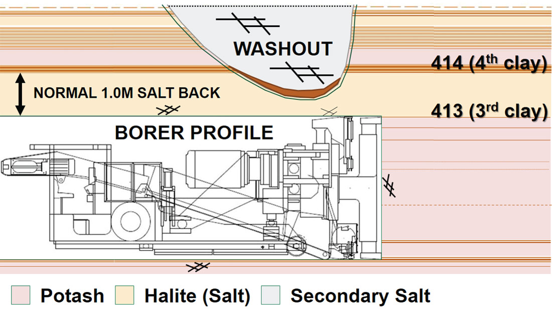
Stress-Relief Mining involves the use of short-term sacrificial mine rooms to draw the mining-induced high horizontal stresses away from nearby long-term entries. This significantly increases the time frame before the roof will deteriorate. The method was pioneered in Saskatchewan and has made potash mining in the province safer. In fact, in areas of normal geological conditions, the Stress-Relief Mining method has mostly eliminated the need for the installation of rock bolts and other ground support for the salt-beam (for further information refer to Jones and Prugger, 1982). Small localized geological anomalies that disrupt the normal bedded rock sequences are routinely encountered (Figure 2) in mining rooms. These anomalies often result in a thinner-than-normal beam in the salt-beam. In these circumstances, ground conditions can become hazardous and rock-bolting is often relied upon to help stabilize the salt-beam. Crews are well trained on how to recognize hazardous conditions; however, we came to realize that subtle geological changes, with potential for causing Serious Injuries or Fatalities (SIF), were not always recognized. What follows is a description of how we developed standardized mining practices and GPR technology to minimize these SIF potentials.
Development of Standardized Mining Practices
On the 24th of February, 2013, at the PotashCorp Cory mine, the night shift was beginning to mine a new entry when one of the miners noticed some unusual deformation developing in the roof over the working area. The borer operator was notified and immediately the decision was made that the crew should evacuate the area. As they were leaving the roof failed and a fall-of-ground of several hundred tonnes occurred into the working area. No one was injured but there was significant damage to the mining equipment.
The post-accident investigation revealed that the salt-beam was 60 cm or less in thickness in many places near the fall-of-ground, rather than the more common 100 cm. Normally, when the salt-beam in the roof is that thin, there are tell-tale signs in the stratigraphy in the mined-out rooms of abnormal geology and rock-bolts are installed to maintain the roof integrity. However, in this case there were no indications that the geology was unusual so normal mining practices were being followed.
The Cory fall-of-ground in 2013 might have resulted in multiple fatalities; fortunately no one was injured. It was recognized that by following normal operating procedures, workers were not able to identify the SIF potential in the working area. The mining industry in Saskatchewan has had an average of one fatality a year for the past 40 years; PotashCorp has historically had a fatality every 2 to 4 years. Our goal is to be one of the safest resource companies in the world, so we asked ourselves “What do we need to do to have an SIF event frequency of zero?” There is no off-the-shelf silver-bullet solution, so we started developing an integrated approach focussing on better standardized mining procedures, more in-depth training, and development and application of GPR technology to help crews recognize when hazardous conditions with SIF potential are developing in the salt-beam. Geoscientists at PotashCorp played a key role in these pursuits because a common factor identified in the mining SIF potential was geology.
PotashCorp operates three conventional mines extracting potash from the A-zone: Cory, Allan and Lanigan (Figure 1). To understand the actual underground mining procedures used at the mines we started the process of reviewing the mining procedures by asking three questions:
- What do the mine sites say they do?
- What do they actually do?
- What should they be doing?
As we investigated the first question (“What do they say they do?”), we found that each site described the geology using different terminology. In other words, there was no common lexicon used to describe the ground conditions. This is due to the history of each site, being originally independent of each other, operated by separate owners. These sites were acquired by PotashCorp in the late 1980s, but aspects of the culture remained unchanged to this day. It’s obvious to Geoscientists how beneficial a common geological language is, but it never occurred to us the importance of this from a safety perspective. By establishing a common geological lexicon across our mines sites, we could ensure that:
- identical names are used for in-mine geological features and anomalies,
- the underground workplace can be described in a common and consistent manner at any site.
To develop the geological lexicon, a technical team led by two geologists was formed. The team brought together mine geologists, engineers and a geophysicist. After consultation meetings and historical research, a lexicon was finalized which gives consistent definitions to eight different kinds of geological anomalies encountered in A-zone mining and specifies key identifiers (attributes) and hazards associated with each kind of anomaly. The lexicon was written such that a person with no geological training could understand the document. This is especially important because often our most important observers are mine personnel, who are working in the geology, but typically have no formal training in geology. If they are to identify the potential geological hazards in their workplace, they must be able understand the language used to help them identify the hazards. Historically, analysis of these geological features was motivated by the need to understand the underlying geological processes that caused the anomalies, and to understand their potential economic impact on mining (Mackintosh and McVittie, 1983). Our greatest pursuit is to ensure the safety of our workers. Therefore, the lexicon was influenced by safety in general and the impact of geology on safety rather than geological influences, such as the root geological causes for the anomalies.
To communicate the lexicon to the workforce, Geology Classification Guides were developed and printed on posters which were distributed at all the mine sites. Photos were included with the drawings to help illustrate the geological concepts in a manner understandable to underground mine workers. All underground mining teams were trained on how to use the guides. Copies of the guides were permanently placed at all lunch tables underground. The lunch tables do not have permanent fixed locations because they move with the mining, yet they function as a “common” area where each crew meets when their shift starts and where they take their breaks. Supplies needed for mining and safety gear are also kept in the area.
To understand the second question (“What do they actually do?”), the team set out to determine if we were practicing what was written in the mining procedures for each site. Underground tours were initiated with an emphasis on engaging in conversations with both mining operators and supervisors. In total, 17 tours were completed over 44 days. It should not be surprising that the conclusion of these tours showed that we were not doing what we said we do (in the written procedures). In other words, our procedures may have been followed at one point in time, but they did not stay current with our mining practices. Actual procedures aren’t static “things”, they change over time due not only to advances in technology or improvements in understanding, but also due to changes in risk tolerance and culture (i.e. baby boomer workforce transitioning to predominantly millennials). Written procedures must be living, peer-reviewed documents.
The third question (“What should they be doing?”) was answered by endeavoring to understand “what are the right things to do?” … to make us one of the safest resource companies in the world. This led to our ‘Ground Conditions Hazard Assessment Standard’ for A-zone mining. This best-practices guidance document was a team effort, which included leadership from the President of Potash, and various levels of executive and mine management ranging from VP’s and General Managers to Operations Superintendents and Chief Mine Engineers. The team also included staff from our Technical Services group and Safety, Health, and Environment (SHE) group. The team was facilitated by a geologist and a SHE expert. Several “brainstorming sessions” were held over a period of three months to gather the input needed for the guidance document. The document was formally recognized as a “Tier 2 Standard” which means that it is a standard in place for a specific mineral (potash in this case) and is approved by the President (of potash) and upper management. Being a standard implies that it must be followed, or amended if needed, as improvements are made, or as oversights are discovered. Support from the executives was critical to achieving success in this endeavor – it might not have been possible otherwise because culture change is never easy.
The Tier 2 Standard had a major impact on ground control strategies, such as installation of rock bolts. It caused us to shift our risk tolerance from being reactive in ground control strategy to proactive, by changing our perception of the severity and influence of geological anomalies towards SIF potential. Now we are installing bolts in ground which used to be considered “safe”. This also required changes to our operations, since the mine sites had less rock bolters than mining crews (i.e. three rock bolters for eight mining crews). Now every mining crew has a rock bolter available, so that the crews aren’t idle while they are waiting for the mobilization of a bolter. This gives the miners an “additional layer of defense” (Conklin, 2012) against falls-of-ground.
The Role of Ground Penetrating Radar
Historically, the mine operators assessed ground conditions by observing the geology they could see. They are very good at recognizing anomalous ground conditions that could become hazardous. It was believed that anomalous ground conditions in the salt-beam, above the mining room, would have stratigraphic indicators or markers in the visible geology in the mining rooms. Typical indicators of anomalous geology would be compressed clay seams, salt intrusions, or disturbed geology. At the location of the Cory fall-of-ground from February 2013, there were no obvious, telltale signs of a thin salt-beam. Even by adopting a policy of proactively installing rock-bolts, we may not have prevented this fall-of-ground because the geology was considered “normal” (i.e. rock-bolts aren’t installed in normal geology). This led us to pursue installation of Ground Penetrating Radar (GPR) devices on the mining machines.
GPR has been actively tested in potash mines for some 40 years. Initial investigations focussed on mapping the geological stratigraphy and assessing potential hazards for water influx. The first applications of the underground GPR method at potash mines began in 1976 by Dr. Don Gendzwill (University of Saskatchewan) and Dr. Peter Annan (Sensors & Software). These initial trial results were reported by Annan et al. (1988). Funk et al. (2016) summarize the past 15 years of GPR technology advancements in Saskatchewan potash mines.
In general, GPR is an excellent tool for imaging the stratigraphy in the overlying salt due to the very dry and homogeneous salt. With typical dielectric constants ranging from 5 to 6, the salt is practically opaque to GPR. In the A-zone potash mines, the 414 clay seam above the beam of salt has a typical thickness of 10 cm to 15 cm (Figure 2). Frequencies of 250MHz and higher do not penetrate through this clay seam, so such GPR devices are not able to image stratigraphy above the 414 clay seam. However, with respect to mine operations, the primary concern is the thickness of the salt-beam itself, which is defined by the thickness of the salt member between the roof and the 414 clay seam. As such, high frequency GPR devices (typically 1000MHz) are well suited for imaging this clay seam. GPR data consists of time records of propagated EM pulses, with typical transit times being in the tens of nanoseconds. Conversion to depth is straight-forward, using the velocity of 0.12 m/ns to convert to depth.
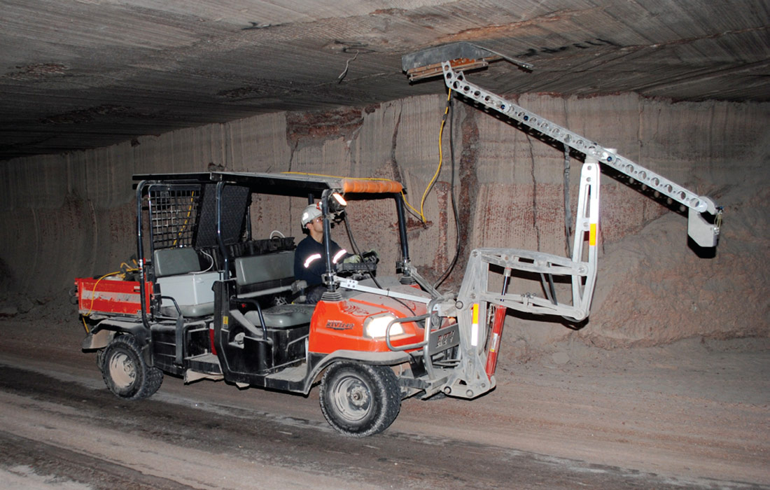
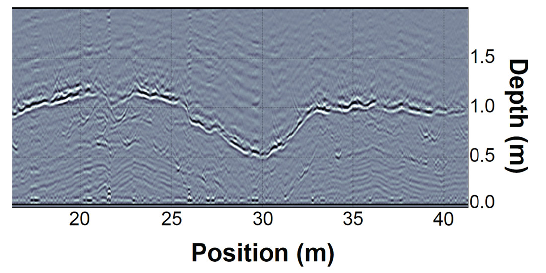
We have found that the highest quality GPR data is obtained by using ground coupled antennas. This approach ensures maximum energy transfer into the ground and minimal energy leaking into the surrounding air. An example of a ground-coupled 1000 MHz Noggin GPR antenna mounted on a Kubota ATV (GPR-RTV) is shown in Figure 3. Such configurations allow for rapid collection of upward looking high quality GPR data that can be used to identify hazardous conditions in the overlying salt (Figure 4). Development of the GPR-RTV is discussed in Funk et al. 2016. GPR-RTV’s make collection of GPR data relatively easy, but they do not solve the challenge of collecting GPR at active mining faces where the fall-of-ground hazards are more significant. Mining machine mounted GPR effectively addresses this need.
The main purpose for mounting GPR on an active mining machine is to give the operator real-time measurements of the salt-beam thickness above the working area. Placing a GPR system in such an environment is challenging but not insurmountable. Several attempts have been made, over the past two decades, to obtain a fully functional real-time GPR unit on an active mining machine. The prototypes were unsuccessful; eventually all of them were severely damaged and rendered inoperable by the normal mining operations. Furthermore, even when the units were working, the interference from the back-scattered EM waves bouncing off the metal on the mining machine completely obliterated any useful signals.
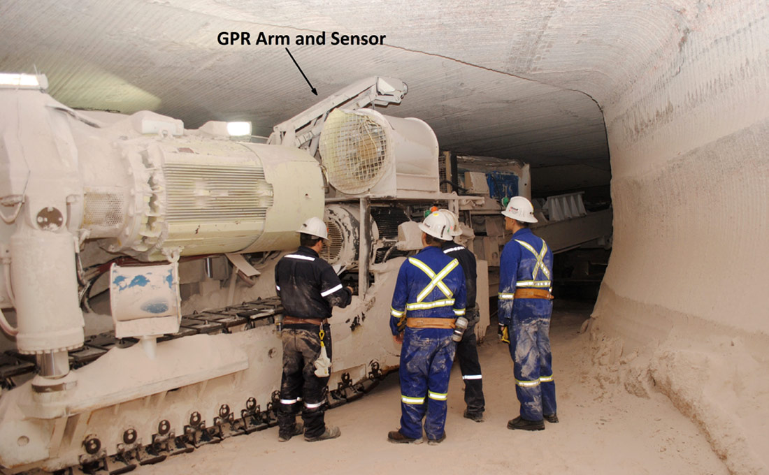
After the February 2013 fall-of-ground at the Cory mine, we decided to pursue development of a new prototype system for collecting GPR from an operating mining machine. The mechanical portion of the prototype was somewhat like the landing-gear on an airplane in that it deploys when needed, but is otherwise tucked safely away (Figure 5). The GPR sensor only needs to be deployed while mining (grinding out ore from the rock-face) and tucked away to prevent damage to the sensor during maneuvering operations. The degradation in signal quality from the back-scattered EM waves was overcome by incorporating shielding into the sensor housing. A Sensors & Software Noggin 1000MHz GPR sensor was mounted inside a rectangular steel container with an open top. The top of the container was covered with a thick high density wearproof polyethylene cover. The interior of the container was lined with radio frequency absorbing material. This material absorbs any EM waves that are not traveling into or out of the salt-beam. This absorbing material is perhaps one of the most important components of the design as it allows for collection of exceptionally clean (high signal to noise) GPR data. Previous systems we experimented with were never able to collect such exceptional GPR data while mining. Real-time GPR images of the strata above the borer in the freshly cut room are displayed in the operator cabin. Within six weeks of the fall-of-ground, the prototype was built, installed and collecting excellent GPR data (refer to Funk, Brewster, and Brehm, 2016 for further discussion).
The overall goal for this project is to provide the miner operator with real-time salt beam thickness, which can warn of actively developing ground hazards in the salt-beam. To adequately meet the goal, a certain level of sophistication had to be built into the GPR software. In general, the quality of the GPR data has been exceptional, and with some training, borer operators become proficient at recognizing developing hazards. The high-quality data allowed for the incorporation of an automated picking algorithm into the GPR software. The algorithm identifies the main clay seam of interest in the GPR data and actively follows the seam as new data come in. From this information, the software can display the salt-beam thickness in the salt-beam above the borer. If the salt-beam becomes too thin (per design limits) an alarm condition is raised and the operator is notified. At that instance, further assessment is carried out and the operator will execute recommended ground control procedures.
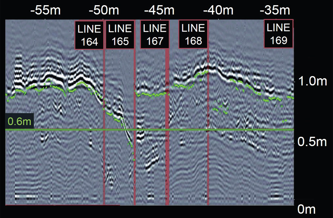
In parallel with installations of GPR systems on the borers, crews were trained on how to use the technology. A typical training session for a crew would take about half a day. Anecdotally, the borer mounted GPR is not unlike a fish finder on a boat. From our experience, we found that the crews warm-up to the technology quickly. For example, on April 21, 2015, an operator at the PotashCorp Cory Mine successfully used the GPR to recognize the development of a thinning salt-beam in an advancing mining face (Figure 6). Per ground control procedures, such a situation required either abandonment or installation of pattern rock-bolting. The operator discussed the situation with his supervisor and the decision was made to abandon the mining face and barricade it off. Such success stories give the technology credibility amongst the crews, leading to further acceptance. This is an excellent example of how the GPR technology, in combination with robust procedures, is used to reduce SIF potential at the mining face.
Conclusion
The development of the standardized mining practices and borer mounted GPR has been a major success; the implementation required the collaboration and commitment of many individuals from several disciplines. The buy-in from the operating crews is a testimonial to the solution’s efficacy and practicality.
This work started by recognizing that a change in culture was needed across our company if we were to make our mining operations safer. It’s still ongoing because culture doesn’t change quickly. Our moment of epiphany was when we came to realize that accidents can’t be engineered out of our processes: accidents will occur. So, we added levels of control that give us better defenses – they give us a soft landing when an unusual condition which could lead to an accident happens. GPR systems mounted on our borers and proactive rock-bolting are the additional levels of control in our processes. GPR also provides the operators with information they need to make informed decisions of developing hazards in real-time, instead of having to rely on external, specialized analysis (typically from geophysicists, who may not be available when the borer operator encounters a developing geological hazard).

Acknowledgements
We would like to thank the executive management at PotashCorp for their support, and Dr. Arnfinn Prugger, VP Technical Services at Potash- Corp, for his critical review of this paper.
Related Reading


Join the Conversation
Interested in starting, or contributing to a conversation about an article or issue of the RECORDER? Join our CSEG LinkedIn Group.
Share This Article