It’s fun to speculate how we’d do in that cliché sci-fi situation, the post nuclear holocaust, à la Mad Max. I imagine we all would be hopeless in terms of being able to recreate various implements, gadgets, devices and technologies which we take for granted. Probably the most self-reliant and resourceful people I’ve seen are the Kiwis – the average New Zealand farmer could probably make a radio or hydroelectric power generator out of stuff pulled from a garbage dump. But I think that’s a temporary situation because they were forced to make do and repair old stuff back in the days when their only real trading partner was Britain; that exclusive trade arrangement ended when Britain joined the European Economic Community.
Recently I was shocked at accounts of the high mortality rate among the early (1600's) English colonists in the Chesapeake Bay area. Many of them starved, despite the fact they were living in one of the world’s richest ecosystems in terms of edible protein. One reason (among others) was that they were unable to adapt their existing technologies, or develop new ones, to allow them to exploit available resources.
In this article I’ll take a look at how a few technologies commonly found in the average office work – the fluorescent light, the microwave oven, and the refrigerator.
The fluorescent light (Fig. 1) is a relatively simple device, but has a few interesting and tricky features. Gas and mercury vapor held within the light bulb is electrically charged, and the excited gas emits UV light; the UV light in turn causes a phosphorous coating on the inside of the bulb to emit light in the visible bandwidth.
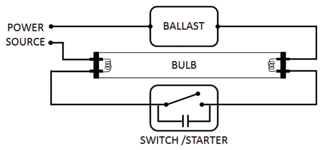
Each of the parts has to be designed and built quite specifically for the lamp to give off useful light and work efficiently. The pressure inside the bulb must be low (~0.3% of atmospheric pressure), requiring the ability to seal the bulb and evacuate the air inside it. The evacuated bulb must contain a certain amount of mercury and a low volume of inert gas – typically argon, neon, xenon or krypton. The electrodes, usually made of coiled tungsten, are designed to give off electrons; in order to achieve this they are coated with a mixture of barium, strontium and calcium oxides. The bandwidth of light is determined by the type of phosphors coating the inside of the bulb. Most commercially available bulbs use a mixture of metallic and rare-earth salts. The manufacturing processes to bond the right grain size of phospors to the glass tube are quite complex.
The critical piece is the ballast – as current flows through the lamp the resistance drops, which if uncontrolled would allow more and more current to pass through. With a constant voltage power source this would result in self-destruction. To counterbalance this effect, the ballast keeps the current flow at an optimal level.
Would the average Joe be able to construct a fluorescent light from scavenged materials? I highly doubt it – almost every piece of a fluorescent lamp requires highly sophisticated materials and manufacturing processes.
The microwave oven, that ubiquitous device used for heating lunches in offices around the world, is quite mysterious. I’d bet only a small fraction of people have a clue how they work, although most of us have a vague idea that it is the water molecules inside food that are being heated by some kind of radiation, microwave radiation the deeper thinkers among us would guess. The devices do indeed output microwave radiation, which is usually centred around 2.45 gigahertz, a wavelength of about 12 cm. Molecules of water, fat, sugar and others which are electric dipoles, are affected in a certain way when placed within the alternating microwave electric field. Dipoles can be viewed as having a small positive charge at one end of a pole, and a small negative charge at the other; these dipoles try to align themselves with the continually flipping magnetic field, and so they start to rotate. Their spinning brings them into contact with other molecules doing the same thing, and heat is generated kinetically. Typically the outer 2 cm to 4 cm of solid foods is heated in this way.
How are the microwaves generated? A cavity magnetotron is the critical piece. This is a relatively simple device, yet an extremely advanced understanding of electromagnetics would be required to converge on its design, let alone its construction. It was first designed and built by secret WWII research efforts in Britain, aiming for improved radar technology. A simple comparison to explain its basic operation can be used: if you blow across the open top of an empty pop bottle, you can create sound waves of a resonant frequency. The cavity magnetotron does the same thing but with EM waves.
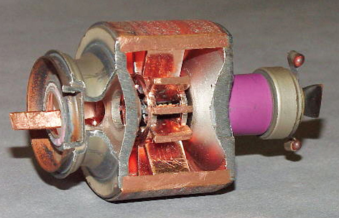
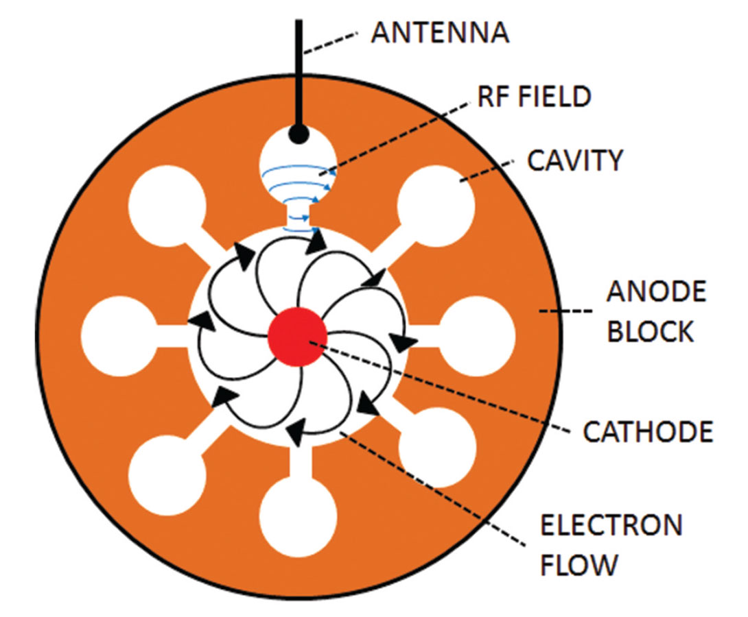
Figure 2 shows a cut open magnetotron. The large copper housing is the anode, and a high voltage cathode runs through its middle. Normally the flow of electrons would be directly and radially outwards, from cathode to anode. However, a large magnet (not shown), creates a linear magnetic field parallel to the cathode, and the resulting Lorentz force causes the electrons to travel outwards in a spiral, where they flow across the opening to the cavities within the anode block. This induces high frequency radio field resonance within the cavities; the RF field is captured by antennae, which are connected to a wave guide. The wave guide sends the extracted microwaves to the cooking chamber of the microwave (or the antenna in a radar device).
Funny to think that a mechanism designed to detect Nazi airplanes is now making popcorn for the great-grandchildren of its inventors. Would any of us be able to build our own microwave oven, to make popcorn in an eerie, glowing, post-nuclear apocalypse world? Highly unlikely, but then again, we’d probably have bigger issues on our hands.
That leaves us with the refrigerator, noble preserver of office lunches and unidentified moulds...maybe we’d have a chance at building a crude version of this. At the heart of every refrigeration device is a heat pump, and they come in various designs, some fairly simple. I’ll describe the type commonly found in domestic refrigerators, which uses a vapour compression cycle technology.
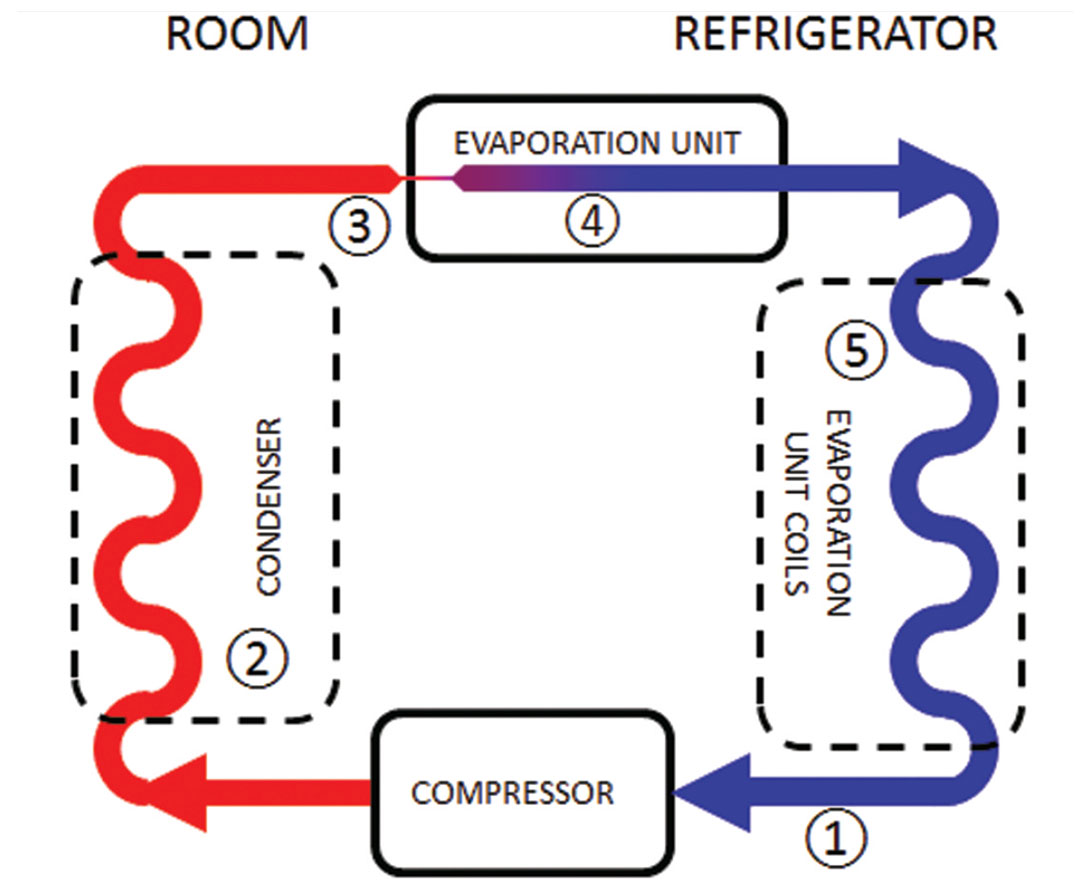
The system is basically a closed two-sided loop, with a refrigerant – typically tetrafluoroethane or R-134a as it is commonly referred to – circulating through the loop. Let’s follow the refrigerant around the loop, starting inside the refrigerator, with the steps below referencing Figure 4.
- The R-134a enters a compressor as a low pressure vapour at just above the temperature of the inside of the fridge. The compressor pressurizes the liquid, which turns it into a super heated vapour.
- The hot vapour exits the compressor and enters a heat exchange coil known as the condenser, which is the metallic grill you can see on the back of most fridges. The heat is dissipated into the room air surrounding the condenser, and as it loses its heat it liquifies. This liquid is about room temperature when it leaves the coil.
- The room temperature liquid then goes through an expansion valve, which basically involves forcing the liquid through a pin hole sized section in the pipe into a much lower pressure section, known as the evaporation unit, the other side of the valve.
- When the liquid squeezes through the expansion valve and emerges into the evaporation unit, about half of the liquid evaporates really quickly, almost explosively, and in doing so draws much of the heat from the remaining ~50% of liquid. That super cooled part vapour / part liquid R-134a then continues through coils within the evaporation unit.
- As the refrigerant passes through the evaporation unit coils, air from the refrigerator is blown across the exterior of the coils. The heat from that air is transferred through the coils and into the refrigerant, which then fully vapourises; the cooled air is then sent back into the refrigerator which gets colder. This marks the end of the cycle, which repeats itself as the vapourised refrigerant re-enters the compressor.
The reason I believe that humans with some scientific knowhow could build a functional refrigerator is that they were being built prior to the advent of electrical systems. The compressor unit can be driven by any form of energy, for example a water wheel, or a steam engine. A broad range of substances can be used as the refrigerant, although obviously most would not be as efficient as R-134a! Additionally, there are different types of refrigeration systems, including some that use brine, and others that use ammonia. They pretty well all exploit the basic thermodynamic principles described by Boyle’s Law, which is fairly well understood, at least in a general sense, by people with an interest in science. Overall though, I don’t give the average modern citizen much of a chance when it comes to using MacGyver-like survival skills, myself included!
References
Gilbert, B. (2007, October). The Gears of Genius. Retrieved March 10, 2013, from Institute of Electrical and Electronics Engineers, Inc.: http://www.ieee.org/portal/site/sscs/menuitem.f07ee9e3b2a01d06bb9305765bac26c8/index.jsp?&pName=ss%20cs_level1_article&TheCat=6010&path=sscs/07Fall&file=Gilbert.xml
Wikipedia. (2013, March 3). Cavity magnetotron. Retrieved March 10, 2013, from Wikimedia Foundation, Inc.: http://en.wikipedia.org/wiki/Cavity_magnetron
Wikipedia. (2013, March 2). Fluorescent lamp. Retrieved March 10, 2013, from Wikimedia Foundation, Inc.: http://en.wikipedia.org/wiki/Fluorescent_lamp
Wikipedia. (2005, May 5). Magnetron2.jpg. Retrieved March 10, 2013, from Wikimedia Foundation, Inc.: http://en.wikipedia.org/wiki/File:Magnetron2.jpg
Wikipedia. (2013, March 10). Refrigerator. Retrieved March 10, 2013, from Wikimedia http://en.wikipedia.org/wiki/Refrigerator


Share This Column