Introduction
Most sedimentary rocks are anisotropic. Most sedimentary basins are nonuniform. Consequently, exploration seismologists benefit from knowledge of these properties. This knowledge provides us with rock-physics information and also enables us to account for the effects of anisotropy and nonuniformity on seismic imaging.
Anisotropy and nonuniformity are conveniently studied in the context of continuum mechanics. Aki and Richards (1980) at the beginning of their classic book, while referring to certain standard conjectures used in seismology, write “[t]hese conjectures, and many others that are generally assumed by seismologists to be true, are properties of infinitesimal motion in classical continuum mechanics for an elastic medium with a linear stress-strain relation”.
This tutorial presents aspects of a scientific foundation for the study and interpretation of seismic wave phenomena in linearly elastic, anisotropic, nonuniform continua. It draws on continuum mechanics and the asymptotic ray theory and presents the applicability and limitations of methods resulting from these two theories.
On Elasticity and Continuum Mechanics
Glossary of selected terms
A material is anisotropic if, at a given point, its properties depend on direction. In seismology, anisotropy refers to the fact that, at a given point, the propagation velocity of a signal varies with direction. Shale is an example of a material where the velocity of a signal along the laminations is different from the velocity perpendicular to the laminations.
A material is nonuniform if its properties depend on position.1 In seismology, nonuniformity refers to the fact that the propagation velocity of a signal varies with position. For example, in layered media the velocity of a signal is different in different layers.
A material is elastic if all the energy expended in deforming an element of this material is stored in the deformed element as potential energy. This potential energy is referred to as strain energy. In other words, the energy expended in deforming an element is not transformed into another form of energy, such as heat. Rather, upon removal of the deforming load, the potential energy causes the element to return to its original form. When considering seismic waves, we often assume that the material through which the waves propagate is elastic. This assumption is used throughout this tutorial.
A material is characterized as a continuum if it is completely described by its mass density and constitutive equations. Constitutive equations describe the relationship between load and deformation.
Physics and continuum mechanics
Continuum mechanics is based on the assumption that a material is continuous at all scales. In other words, continuum mechanics disregards the details of the granular or molecular structures of materials. These microscopic structures are considered only as average properties that are studied through macroscopic investigations. For instance, in investigating the bending of a rod, we study deformation as a function of applied forces without considering the interrelation amongst the molecules that form this rod. Such an approach provides us with a convenient formulation that, for our purposes, yields sufficiently accurate results that are consistent with those obtained by fundamental physical considerations (e.g., Aoki et al., 2000).
Thus, we choose to describe seismic phenomena in the context of linearly elastic, anisotropic, nonuniform continua. Before discussing wave phenomena in such continua, let us consider the ramifications of our formulation.
Specifically, in physics, anisotropy – at some scale – is rooted in nonuniformity. However, having chosen the convenience of continuum mechanics, we describe the macroscopic behaviours of materials by considering anisotropy and nonuniformity as two independent properties.
Anisotropy and nonuniformity
We gain information about anisotropy and nonuniformity of a material from the elasticity constants that describe a given continuum. A three-dimensional, linearly elastic, continuum is described by the constitutive equations that relate six stress-tensor components to six strain-tensor components by thirty-six elasticity constants. For convenience, we can write these constants as a 6x6 matrix,
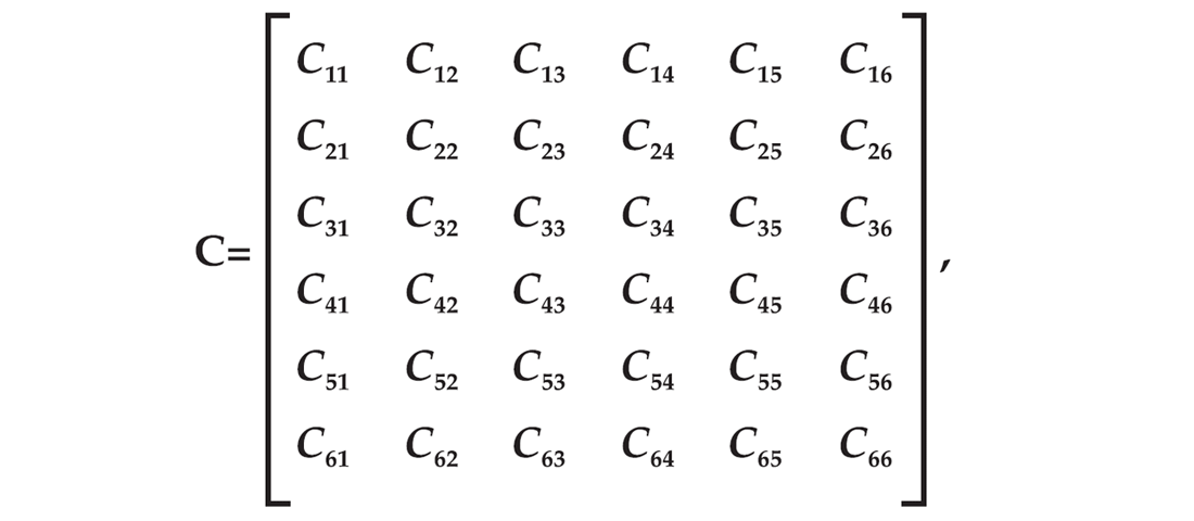
referred to as the stiffness matrix.
In general, due to the existence of the strain energy, the stiffness matrix is symmetric. Hence, there are only twenty-one independent elasticity constants, namely,
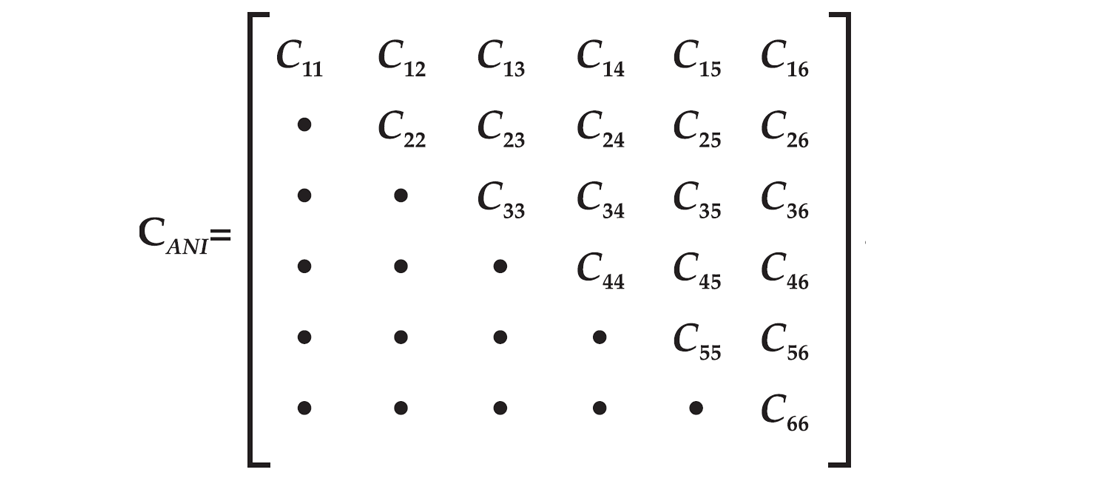
In other words, Cmn = Cnm. Thus, the description of a linearly elastic continuum in an arbitrary coordinate system requires twenty-one independent elasticity constants.
The elasticity constants relate the components of the stress and strain tensors, which account for arbitrary orientations of forces and deformations within the continuum (e.g., Malvern, 1969). Hence, the stiffness matrix inherently contains a directional dependence. In other words, the stiffness matrix describes the anisotropy of a given continuum.
Furthermore, the elasticity constants give us insight into the uniformity of the continuum. If the elasticity constants are the same for all points of a continuum, the continuum is uniform. If the elasticity constants are a function2 of position, the continuum is nonuniform.
Material symmetries
The symmetry of a material is determined by the number of independent elasticity constants required to describe a given continuum. If we are dealing with a linearly elastic, isotropic continuum, its description in an arbitrary coordinate system requires only two independent elasticity constants. In such a case, the stiffness matrix becomes
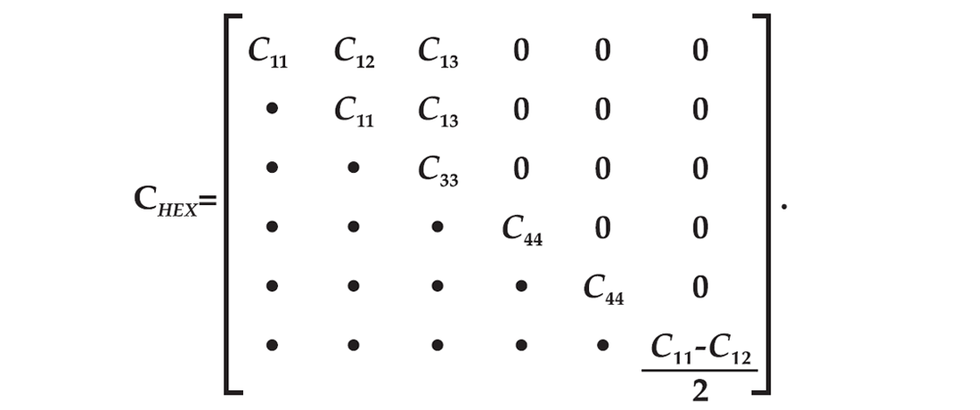
It is common to express the elasticity constants of an isotropic continuum in terms of the Lamé parameters, which are defined as
λ: = C11–2C44, and μ: = C44.
The immediate physical application is illustrated by the fact that μ describes the rigidity of a material; its vanishing implies that the material has no resistance to a change in shape. Hence, μ is often referred to as the rigidity modulus.
If we are dealing with any linearly elastic, anisotropic continuum, its description in an arbitrary coordinate system requires the stiffness matrix CANI. However, by properly orienting the coordinate axes, the number of nonzero, independent elasticity constants of a general anisotropic continuum can be reduced from twenty-one to, at most, eighteen (e.g., Winterstein, 1990). Acoordinate system that allows such a reduction is called a natural coordinate system. At times, a given physical setting, e.g., layering, fractures, etc., suggests a natural coordinate system. At other times, finding such a system can be a difficult task. However, it can be rigorously shown that such a system always exists (e.g., Helbig, 1994).
Let us work in a natural coordinate system to consider different materials exhibiting different symmetries. If we require all eighteen elasticity constants to describe a given continuum, the continuum belongs to the triclinic symmetry class. Several other symmetry classes exist. For instance, if we require nine independent elasticity constants, the continuum belongs to the orthorhombic symmetry class. An illustration of laboratory measurements using a natural coordinate coordinate system to describe an orthorhombic material is shown by Cheadle, et al. (1991). In their experiment, the orientation of the natural coordinate system is indicated by the texture of the synthetic material.
In applied seismology, particularly while dealing with sedimentary basins, we often describe anisotropic materials in terms of five independent elasticity constants. The corresponding continuum belongs to the hexagonal symmetry class.
Hexagonal symmetry class
A continuum belonging to the hexagonal symmetry class is described by its mass density, ρ, and five independent elasticity constants. In a natural coordinate system, the corresponding stiffness matrix is given by
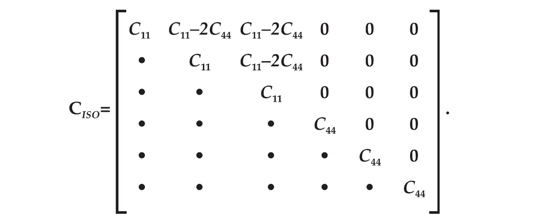
In linear elasticity theory, hexagonal symmetry possesses an important property. Any linearly elastic, hexagonal continuum possesses a rotation-symmetry axis. Let us consider an xyz-coordinate system. Let the z-axis be the rotation-symmetry axis. It can be shown that the properties associated with any plane that contains the z-axis are the same. Thus, with no loss of generality, we can set y = 0 and describe the three-dimensional continuum using the xz-plane.
In the context of applied seismology, hexagonal symmetry is particularly useful when considering horizontal layers, where the vertical cross-sections along all azimuthal directions yield the same results. For the layered case, the rotation-symmetry axis is perpendicular to the layers. Hence, such continua are referred to as being transversely isotropic.
On Wave Phenomena In Elastic Continua
Wave propagation in anisotropic continua
To describe the propagation of a disturbance in an elastic material, we combine equations of motion, which are a consequence of conservation of momentum, with the constitutive equations of a linearly elastic continuum to obtain the elastodynamic equations. For plane-wave solutions, we can show that in an elastic, anisotropic continuum, there are three wave types that propagate with three distinct velocities (e.g., Love, 1892).
For instance, for wave propagation in a linearly elastic, hexagonal continuum with the z-axis being the rotation-symmetry axis, Thomsen (1986) expresses the mass density and the elasticity constants in terms of five parameters given by
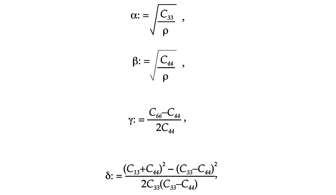
and

The immediate seismological application is illustrated by the fact that α is the magnitude of the P-wave velocity along the rotation-symmetry axis, while β is the magnitude of the S-wave velocity along the rotation symmetry axis. Also, the expression for γ can be rewritten as

where the numerator is the difference of the squared magnitudes of the horizontal and the vertical velocities of SH waves. Analogously, dividing both numerator and denominator by the mass density, ρ, in the expression for ε, we can rewrite the numerator as the difference of the squared magnitudes of the horizontal and the vertical velocities of P waves.
In the particular case of isotropy,

as expected from the well-known expressions for the P-wave and S-wave velocities, respectively, where λ and μ are the Lamé parameters. Also, examining the entries of the stiffness matrix CISO, we immediately see that in the case of isotropy we obtain γ = δ = ε = 0. If these parameters are nonzero, the continuum is anisotropic and, hence, they are often referred to as the anisotropy parameters. The vanishing of the anisotropy parameters for isotropic continua and their being small for weak anisotropy allows us to conveniently approximate otherwise awkward phase-velocity expressions using a Maclaurin-series expansion in these parameters.
Considering the linear terms of the Maclaurin series in the anisotropy parameters, we can approximate the three distinct phase velocities by

and

where the subscripts qP, qSV and SH refer to quasi-P, quasi-SV and SH waves and where θ denotes the phase angle (Thomsen, 1986). Note that in the case of isotropy, where γ = δ = ε = 0, vqP = α while vqSV = vSH = β. Thus, for an isotropic case there are only two distinct velocities and their expressions have no angular dependence, as expected.
Quasi-P and quasi-S waves
In anisotropic continua, seismic waves, in general, are neither pure pressure (P) nor pure shear (S) waves. In general, the expressions for the three velocities corresponding to the three wave types propagating in linearly elastic, anisotropic continua follow from a cubic equation. This cubic equation is the characteristic equation of a 3x3 matrix, whose entries contain elasticity constants and the components of the unit vector normal to the plane-wave solution. In general, a cubic equation has three distinct solutions, corresponding to three distinct eigenvalues. Each eigenvalue corresponds to the phase velocity of a given wave type. Also, for each eigenvalue, we can obtain the corresponding eigenvector. The eigenvector corresponds to the polarization direction of a given wave type.
It can be shown that, in general, the eigenvectors are neither parallel nor perpendicular to the unit vector normal to the plane-wave solution. In other words, the polarization direction is neither normal nor tangential to the wavefront, as is the case in isotropic continua for P and S waves, respectively. In many seismological studies, the deviation from normality or tangency, caused by anisotropy, is sufficiently small that we refer to the corresponding waves as quasi-P and quasi-S waves.
Phase and ray concepts
Wave propagation in anisotropic continua is described in terms of two kinds of velocities, namely, phase velocity and ray velocity. Wavefronts are surfaces of constant phase. Consequently, the orientation of the wavefront is described by the phase angle while the velocity of propagation along the wavefront normal is the phase velocity.
In considering the solutions of elastodynamic equations, we often invoke the asymptotic, high-frequency approximation that results in the concept of a ray (e.g., Kravtsov and Orlov, 1990, Červený, 2001). All formulations of seismic problems that deal with rays belong to asymptotic ray theory. The orientation of a raypath is described by the ray angle while the velocity of propagation along the raypath is the ray velocity.3 We must be aware of the range of applicability and the limitations of the asymptotic ray theory in linearly elastic, anisotropic, nonuniform continua. Grant and West (1965) emphasize this need when they note that “it is often surprising to observe how uncritically [the] validity [of ray methods] in seismological problems is accepted”.
In asymptotic ray theory, in general, at a given point of the wavefront, the direction of the raypath is not parallel to the wavefront normal, as is the case in isotropic continua. To illustrate this, consider a spherical wavefront originating from a point source in an unbounded, isotropic continuum. The unit normal of a plane tangent to the sphere at a given point is collinear with the radius of the sphere, where the radius is tantamount to the raypath, namely, the trajectory followed by a signal between the source and a given point on the wavefront.4 In general, in anisotropic continua, a point source generates nonspherical wavefronts. Consequently, the unit normal of a plane tangent to the wavefront at a given point is not collinear with the raypath connecting the source and the point in question.
Also, in general, unlike for isotropic continua, there is no collinearity or orthogonality among wavefront normals, raypath directions and polarizations. In the previous section we described the quasi-P and quasi-S waves as being polarized in the direction that is neither parallel nor perpendicular to the wavefront normals. We can also describe quasi-P and quasi-S waves as being polarized in the direction that is neither parallel nor perpendicular to the raypaths.
Furthermore, in general, the magnitude of velocity along the wavefront normal is different from the magnitude of the signal velocity along the raypath. Within the asymptotic approximation, energy propagates along the raypath (e.g., Born and Wolf, 1959); hence, traveltime measurements of a seismic signal between a point source and a point receiver are intimately related to the velocity along the raypath.
Traveltimes and raypaths in anisotropic, nonuniform continua
The key seismic measurement is the traveltime of the signal between the source and the receiver. This traveltime is a function of both the anisotropy and nonuniformity of the material. We make numerous assumptions while processing and interpreting seismic data. Consequently, it is important to be aware of the consequences and limitations of these assumptions.
It can be rigorously shown that in a uniform continuum the raypaths are always straight. In other words, anisotropic properties of the material affect the traveltime measurement, but the presence of anisotropy does not affect the shape of the raypath in a uniform continuum. Consequently, having measured the direct-arrival traveltime in a VSP survey, we can uniquely describe the velocity of the signal along a given straight raypath. If velocity is a function of direction, we can immediately obtain this direction from the source-receiver locations.
It can also be rigorously shown that in a nonuniform5 continuum the raypaths are never straight. Snell’s law of refraction is an illustration of this property. Consequently, having measured the direct-arrival traveltime in a VSP survey, we cannot uniquely describe the velocity of the signal along the raypath since the velocity is a function of the trajectory of the signal, which is not known. The presence of anisotropy affects the shape of the raypath in a nonuniform continuum.
Given a velocity field, we can obtain the raypaths between sources and receivers by solving the eikonal equation (e.g., Buchdahl, 1970). An important and convenient corollary of the eikonal equation is Fermat’s principle of stationary traveltime. Consequently, within certain mathematical restrictions due to Legendre transformations, we can obtain the raypath by finding the trajectory along which the traveltime is stationary. In this process, we also obtain the value of the traveltime. This is a forward problem that, in most cases, has a unique solution.
In applied seismology, given the traveltime, we often seek to determine the velocity field. The crux of this inverse problem consists in obtaining the raypath. In most cases, the solution is not unique. This nonuniqueness is particularly pronounced in the studies of anisotropic and nonuniform materials, where at every point of the continuum, the signal velocity is a function of both direction and position.
There are several methods that allow us to study such inverse problems (e.g., Bleistein et al., 2001). However, even if we obtain a solution, the nonuniqueness of solutions as well as many other limitations of various approaches remain. Consequently, an exploration seismologist must be aware of these difficulties.
Reflection and transmission coefficients
Apart from the traveltime, the second key seismic measurement is the amplitude of the signal. It provides important information about the physical properties of rocks. In particular, the amplitude information is used for, so-called, AVO studies where, given an interface, we investigate the amplitude of the reflected signal as a function of the incidence angle to obtain information about the materials directly above and below the interface. In the context of continuum mechanics, the reflection and transmission coefficients, are functions of angles as well as of elasticity constants and mass densities of the materials above and below the interface (e.g., Mavko et al., 1998). For instance, under the assumption of isotropy, in view of the stiffness matrix CISO, the elasticity constants in question are C11 and C44, while under the assumption of hexagonal symmetry, in view of the stiffness matrix CHEX, the elasticity constants in question are C11, C12, C13, C33 and C44. Consequently, depending on our assumption, from the very outset we are looking for a different set of elasticity constants to describe the material in the immediate vicinity of the interface.
In view of the asymptotic ray theory, the combination of anisotropy and nonuniformity affects the raypath. Hence, both the location of the reflection point and the incidence angle are functions of the mass densities and elasticity constants of the continuum that we use to describe the material through which the signal propagates between the source and receiver. Consequently, depending on our assumption, from the very outset we define the conditions that determine the location of the reflection point and the incidence angle.
Conclusions
This tutorial gives a brief look at aspects of seismic wave phenomena associated with anisotropic and nonuniform materials. Our investigation of seismic phenomena is rooted in two mathematical theories, namely, continuum mechanics and asymptotic ray theory. Both theories are based on abstract concepts. Materials are composed of molecules and therefore, physically, there are no continua. A disturbance in the earth propagates by interaction of molecules and therefore, physically, there are no rays.
The justification of a given continuum-mechanics method and of a given asymptotic-ray-theory method is based on two conditions. Firstly, each method has to satisfy the rigors of a mathematical formulation, in which results follow logically from assumptions. Secondly, the results predicted by each method must, to within the required accuracy, agree with observable physical phenomena. If the first condition is not satisfied, a given method is flawed and must be discarded or corrected. If the second condition is not satisfied, a given method is inadequate and must be discarded or extended.
In this tutorial, we must also be aware of the fact that we ignore certain properties of actual materials, which can be accommodated in continuum mechanics. For instance, no actual material is perfectly elastic and anelasticity can be accommodated in a particular continuum by a more sophisticated formulation of the constitutive equations. Anelasticity also affects both traveltimes and raypaths of seismic signals (e.g., Hearn and Krebes, 1990a,1990b).
The increased accuracy of measurements provided by modern seismic technology necessitates several extensions of current seismic methods. Our data show many physical phenomena that are not properly accommodated by standard methods. In particular, our wish to obtain quantitative results from the interpretation of our data requires rigorous extensions of several standard formulations.
Understanding theories that are implicitly used in seismic formulations allows us to know the limitations of a given approach as well as to evaluate the range of applicability of a given method. Understanding these theories also allows us to extend the resulting methods to accommodate the complexities of the materials. With this understanding we can use continuum mechanics and the asymptotic ray theory to study and interpret seismic data in complex materials.

Acknowledgements
I would like to acknowledge the support of the Department of Earth Sciences, Memorial University of Newfoundland where I hold the Petro-Canada Chair in Applied Seismology and the Department of Mathematics and Statistics, University of Calgary where I am an adjunct associate professor. In addition, I am grateful to PanCanadian Energy and Talisman Energy for their sponsorship and support of The Geomechanics Project.
Also, in the preparation of this tutorial, I would like to acknowledge the constructive criticism received from Ms. Cathy Beveridge and Dr. Raphaël A. Slawinski.


Join the Conversation
Interested in starting, or contributing to a conversation about an article or issue of the RECORDER? Join our CSEG LinkedIn Group.
Share This Article