Summary
In the conventional approach to VSP and surface seismic imaging, the VSP and surface seismic data sets are processed and migrated independently. The VSP image is then spliced into the surface seismic result. Although good images can be obtained in this way (e.g. Hinds et al., 1993; Zhu and Lines, 1994), this method has some drawbacks. First, the portion of the surface seismic image where the VSP image is spliced in is discarded, and secondly, the VSP image may not tie well with the surface seismic image on the first attempt if the velocity model and imaging algorithm used for migration of the two data sets were not exactly the same.
In this work, a new approach to VSP and surface seismic depth migration was developed and tested on both synthetic and field data from the Rocky Mountain Foothills of southern Alberta, Canada. Instead of splicing the VSP image into the section derived from the surface seismic data, a new migration algorithm and a single velocity model were used to migrate both data sets into a common output grid. The two images were then scaled and summed to yield one integrated depth-migrated section. The latter had increased vertical resolution, due to the higher frequency content of the VSP data, and good lateral event continuity, since the same velocity model was used for migration. The image also contained enhanced structural detail, since no part of the surface seismic image had been discarded in the integration process. The use of a common migration-velocity model also assured there were no misties. This resulted in optimum well ties and a robust interpretation.
Method
In order to test this integrated VSP and surface seismic depth imaging approach, a new VSP and surface seismic anisotropic prestack depth migration (PSDM) algorithm was developed. The algorithm, which is diffraction-stack based, can handle anisotropy (VTI and TTI) as well as different wave modes (pure-modes, converted waves and multi-modes). The VSP and surface seismic data sets are migrated separately to a common output grid using the same algorithm and migration-velocity model. The VSP image is then muted and scaled, and summed with the surface seismic image to yield the integrated depth section.
Field Data Example
After the method was successfully tested on numerical data sets (Kirtland Grech et al., 2001a) it was then applied to the field data on which the numerical modelling was based (Figure 1). The field data used in this study comes from the Rocky Mountain Foothills of southern Alberta, Canada. A plan view of the surface seismic line, the VSP well and the shot locations for the multi-offset VSP are shown in Figure 1. The structural geology in the area is characterized by steeply-dipping anisotropic clastics of Mesozoic age, which overlie Palaeozoic carbonates. The exploration target in this case lies in the hanging wall of a thrust sheet in the Upper Palaeozoic.
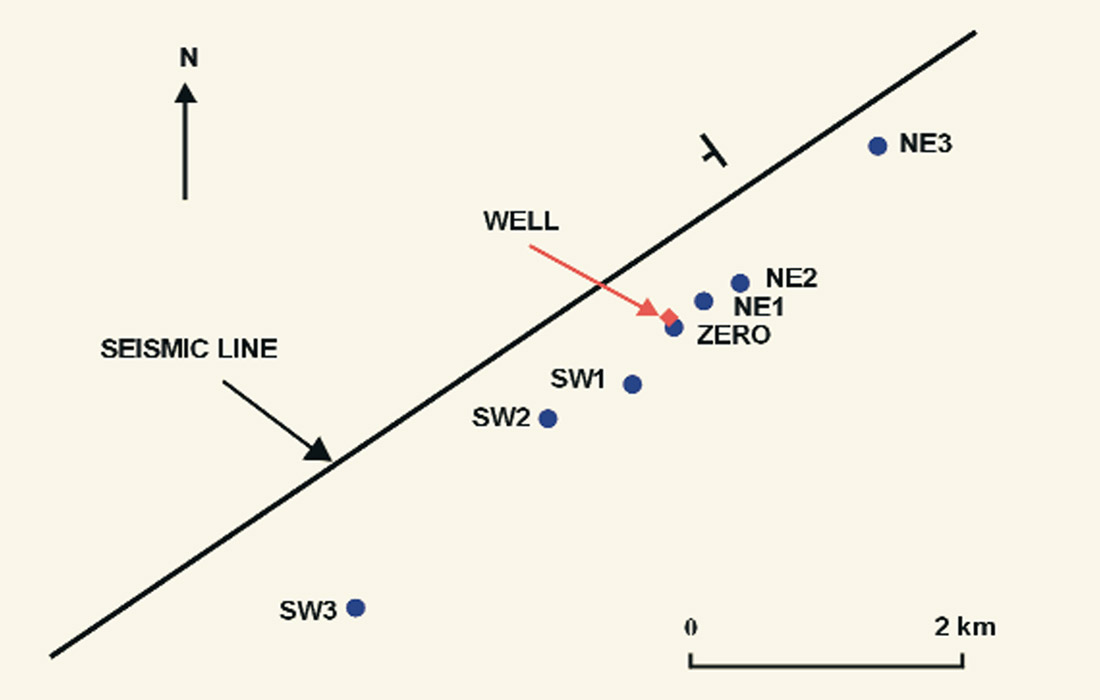
The surface seismic dip line was shot in 1990 for PanCanadian Petroleum, using split-spread acquisition geometry with a shot interval of 100 m and a receiver interval of 20 m. Maximum offset was 3681 m. The multi-offset VSP was acquired in 1999 for Anderson Exploration, using a vibroseis source and a 5-level 3- component tool (Kirtland Grech et al., 2001b). The multi-offset VSP was acquired for two purposes - anisotropy analysis and depth imaging. Whereas data from all the VSP shots were used for anisotropy analysis, only the four shots closest to the well (NE1, NE2, SW1 and ZERO on Figure 1), which were purposely acquired with a smaller tool spacing, were used for depth imaging. Data from these four VSP shots and the surface seismic line were then processed for pre-stack depth migration. Atypical shot gather from each data set is shown in Figure 2.
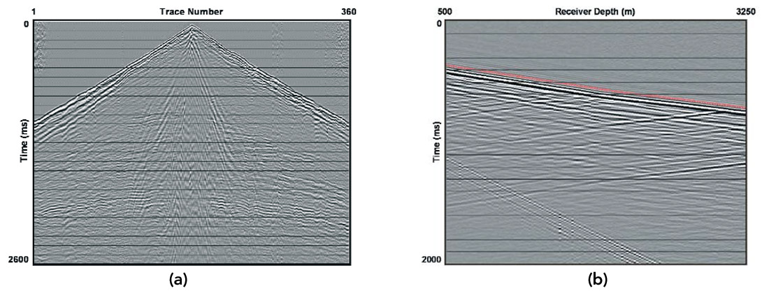
After spectral analysis to determine the frequency content, the data were filtered before migration using a 5/15 - 60/75 Hz bandpass filter for the surface seismic data and a 8/15 -70/75 Hz bandpass filter for the VSP data. The passband is 10 Hz broader for the VSP case to take into account the higher frequency content of the VSP when compared to the surface seismic data. No attempts were made to match the phase of the surface seismic data to that of the VSP.
Isotropic PSDM
The velocity model
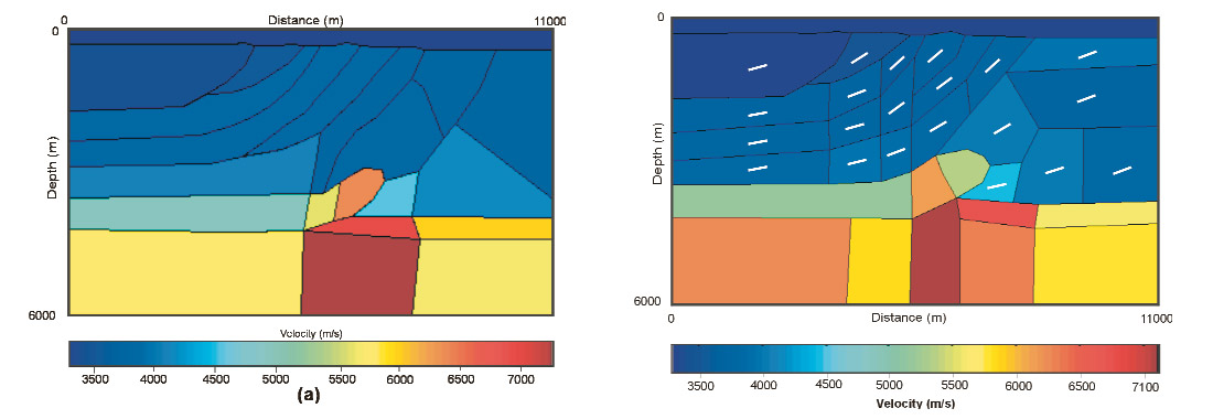
The depth-velocity model used for isotropic migration is shown in Figure 3a. Since the raytracer used for traveltime table calculation is interface-based, the velocity model was divided into small polygons that grouped regions of similar velocities. The velocity model did not include a detailed near-surface velocity layer, so refraction statics were applied to the surface seismic data. Elevation statics were not included since migration was carried out from topography. No shot static corrections were available for the VSP data.
Surface seismic and VSP migration results
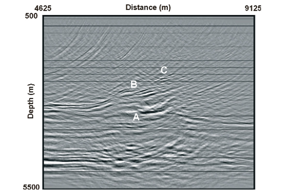
The section obtained after isotropic PSDM of the surface seismic data is shown in Figure 4. There are three main events of interest: a sliver of lower-velocity Jurassic clastics of the Fernie Group that overlies the Palaeozoic carbonates in the footwall of the thrust (A), a thin layer of Fernie clastics on top of the Palaeozoic carbonates in the hanging wall of the thrust (B) and a pop-up structure (C), also in the hanging wall of the thrust.
The four VSP shots were migrated separately using the same velocity model that was used for the surface seismic data (Figure 3a). Each image was normalised by the maximum amplitude within that image and the 4 images were then summed yielding the final image shown in Figure 5. This image was then muted, scaled and integrated with the image obtained from the surface seismic data.
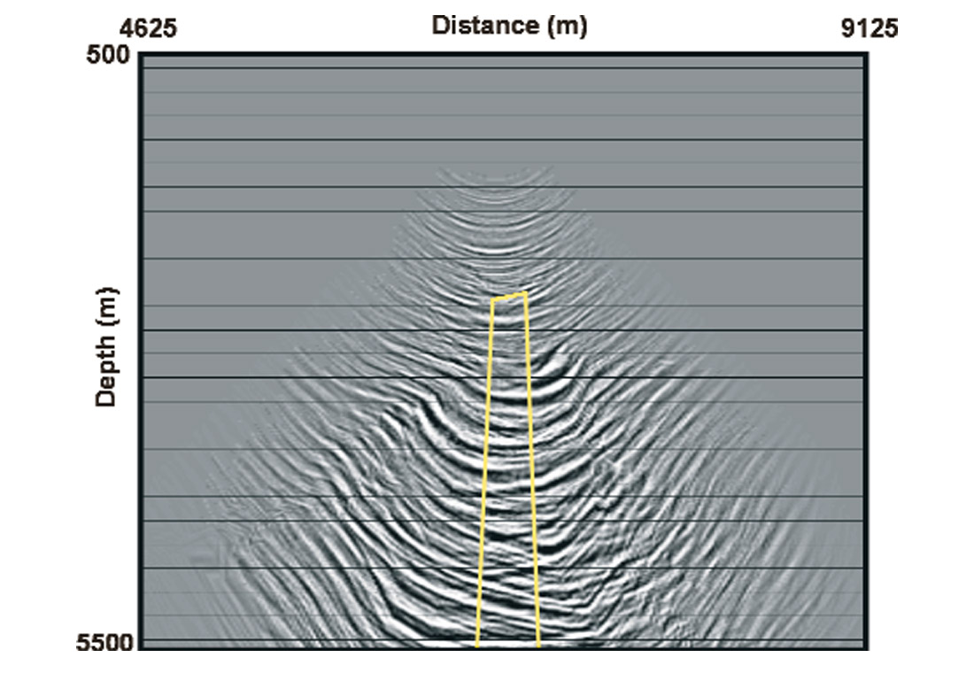
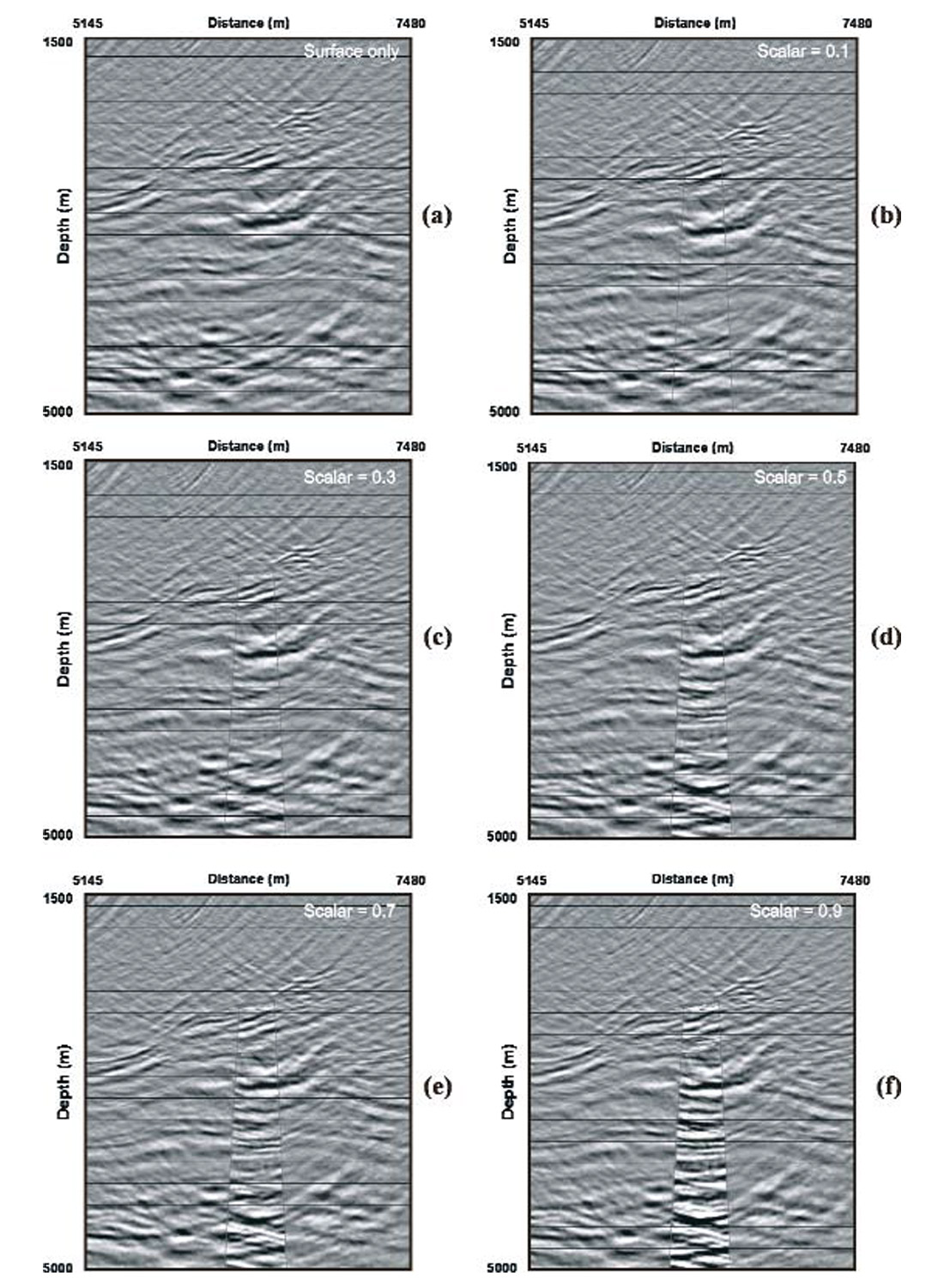
To determine which part of the VSP image has to be muted to eliminate migration artifacts (arising from the limited number of VSP shots) a series of mutes, ranging from broad to narrow, was designed and applied successively to the VSP image. In each case the VSP image was summed with the surface seismic image to determine which mute kept the most VSP data without including the migration artifacts, which degraded the quality of the integrated image if not eliminated. The final mute used in this case is marked in yellow on Figure 5. Before summing, the VSP image was also multiplied by a scalar to yield amplitudes that are at a level comparable to that of the surface seismic image. To determine the optimum multiplier value, the VSP image was multiplied by a set of scalars (ranging from 0.1 to 0.8 in steps of 0.1) and in each case summed with the surface seismic image, to create a whole suite of integrated images. The effect of different VSP scalars on the integrated image can be seen in Figure 6. A scalar of 0.5 was selected for the VSP image, as being the most appropriate to balance the image. The corresponding integrated VSP and surface seismic depth image is shown in Figure 6d. A more quantitative approach to amplitude scaling and a cosine-tapered mute would likely enhance the integrated image.
Spliced versus integrated VSP and surface seismic imaging
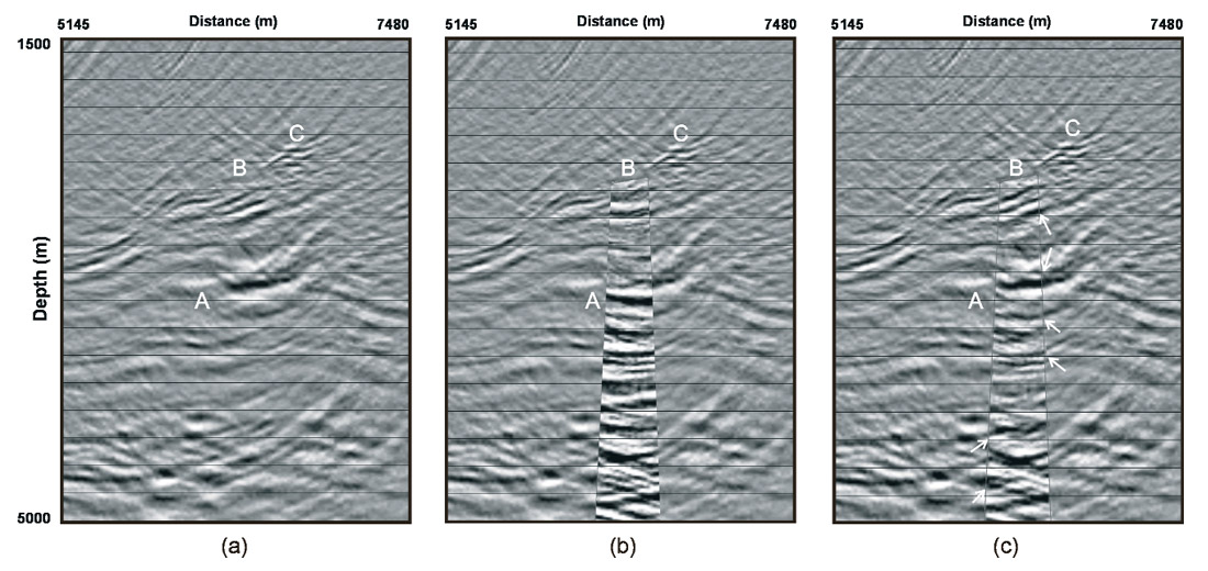
Figure 7 compares the conventional approach to VSP and surface seismic imaging, in which the VSP image is spliced into the surface seismic section (Figure 7b), with the newly developed approach of integrated VSP and surface seismic imaging (Figure 7c). Figure 7a shows details of only the surface seismic depth-migrated section for comparison. The three images concentrate on the area around the exploration target. The three events of interest A, B and C are also labelled. Comparison of Figures 7a and 7b shows improved vertical resolution on Figure 7b in the part where the VSP has been spliced in, due to the higher bandwidth of the VSP data. There is also more structural information on Figure 7b, especially below event A. However, some of the coherent events in the top of the hanging wall at B that are present on the surface seismic section (Figure 7a) are not as well imaged on the VSP image and hence they are also not well imaged on the spliced section (Figure 7b). The integrated VSP and surface seismic depth-migrated section (Figure 7c) shows enhanced structural detail in the part were the VSP has been summed in, both at B and also below A, since it contains contributions from both the VSP and surface seismic data. It also shows higher resolution due to the broader bandwidth of the VSP data, and improved lateral event continuity between the surface seismic image and the part where the VSP has been summed in (some examples are indicated by the arrows on Figure 7c). This makes the integrated image easier to interpret than that shown in Figure 7b.
Anisotropic PSDM
The anisotropic velocity model
Since the dipping Mesozoic clastic strata that overlie the Palaeozoic carbonates were shown to be anisotropic (Kirtland Grech et al., 2001b), the integrated migration was repeated by incorporating anisotropic velocities in the depth-velocity model. The migration velocity model in this case consisted of 4 parameters: the bedding-perpendicular velocity (V0), the stratigraphic dip and the anisotropy parameters ε and δ (Thomsen, 1986). The values of ε and δ used had been previously determined by traveltime inversion of the first arrivals from the multi-offset VSP (Kirtland Grech et al., 2001b). The model was divided into a number of polygons that represented the different dip domains (Figure 3b). The average dip and low velocity (V0) within each polygon were then assigned. The model in Figure 3b is colour-coded to represent the low velocity. The short white lines represent the general dip direction of the beds within each polygon. A value of 0.1 for epsilon and 0.05 for delta were used for the whole clastic sequence.
Anisotropic migration results
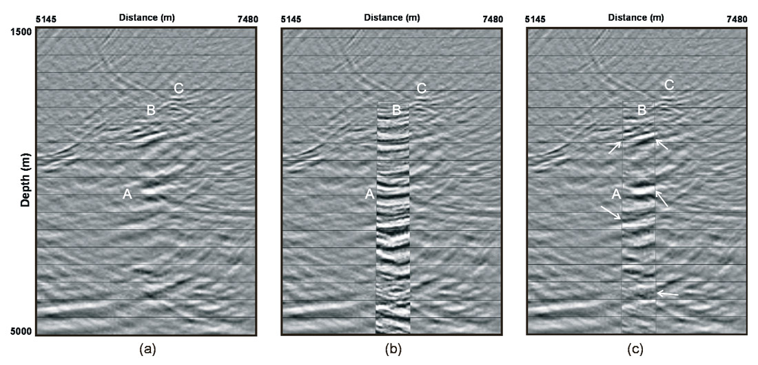
Another three-panel comparison, showing the surface seismic image, the VSP image spliced into the surface seismic result, and the integrated VSP and surface seismic image, all for anisotropic velocities, is given in Figure 8. As with the isotropic images (Figure 7) there is enhanced vertical resolution in the part where the VSP is spliced in the surface seismic image (Figure 8b). There is also more structural detail evident on the full length of the VSP image (Figure 8b) that is not evident on the surface seismic result (Figure 8a). However, it is not easy to interpret the events on the VSP splice and how they tie with the events on the surface seismic image. The integrated image (Figure 8c) on the other hand, not only benefits from the enhanced vertical resolution visible on the spliced image, but also contains more structural detail and good event continuity (some examples are indicated by the arrows on Figure 8c) between the part where the VSP has been summed in and the rest of the image. This again makes the integrated image (Figure 8c) easier to interpret than the one obtained using the conventional approach (Figure 8b).
Comparison of the isotropic and anisotropic panels (Figures 7 and 8)
Comparison of the anisotropic and isotropic migration results reveals some differences in structure, focussing and positioning of events. Whilst the top of the Palaeozoic carbonates in the hanging wall of the thrust has the same structural shape, it is better imaged on the isotropic sections. The pop-up structure (event C), particularly the leading edge, is more clearly imaged on the anisotropic sections. The major difference is exhibited by event A, which shows a change is structural style between the isotropic and anisotropic images. The same event is also better focussed on the anisotropic image. Both the integrated isotropic and anisotropic images show enhanced resolution and more structural detail, in particular below event A, than on the surface seismic migrated-sections. Differences in the positioning of events are described in the next section.
Imaging Improvements and Interpretation
The surface isotropic image, surface anisotropic image, and the integrated VSP and surface seismic image are shown in Figures 9a, 9b and 9c respectively. These three figures show how the image was improved from the initial case of isotropic depth migration of the surface seismic data, first by including anisotropy in the migration and secondly through the integration of VSP and surface seismic anisotropic depth migration. The VSP well is marked in white and the three events of interest, A, B and C, are also labelled.
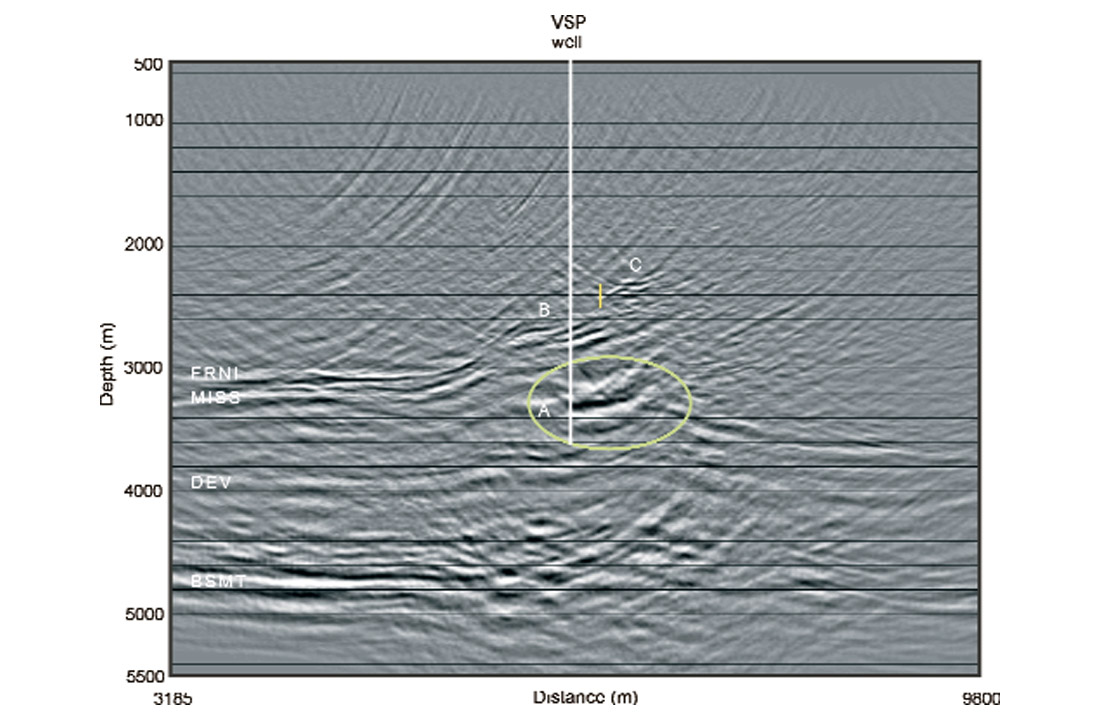
Although the general structural style of the shallower dipping events, the hanging wall of the thrust and the basement is similar on Figures 9a and 9b, there are some major changes in the positioning of events and structural style in the footwall of the thrust and the Devonian. Event A(enclosed in a green ellipse) is not very well focussed and difficult to interpret on the isotropic image (Figure 9a). On the anisotropic image (Figure 9b) the same event can be interpreted as a continuation of the top of the Palaeozoic carbonates in the footwall of the thrust. The reflection from the Devonian on Figure 9b is seen to ramp upwards, suggesting the presence of a detachment. This is not evident on the isotropic image, where the Devonian at the same location appears to have a broad anticlinal shape.
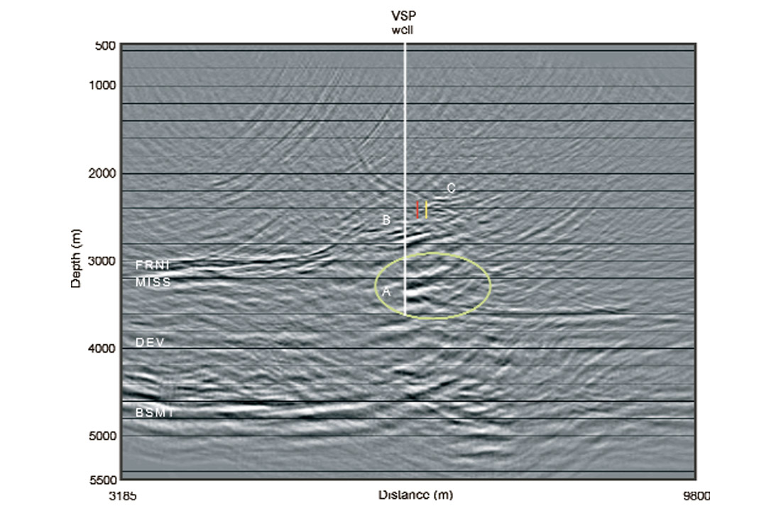
The anisotropic image has also been shifted in the downdip direction of the beds. This is easily seen by comparing, for example, the location of the trailing edge of the pop-up structure in the hanging wall of the thrust (event C) on Figures 9a and 9b. The small, yellow vertical line marks the trailing edge of the pop-up on Figure 9a. The same event on the anisotropic image (Figure 9b) is marked by the small, red vertical line (the location on the isotropic PSDM is shown in yellow for comparison). This shows how the use of isotropic migration code in the presence of anisotropy leads to positioning errors.
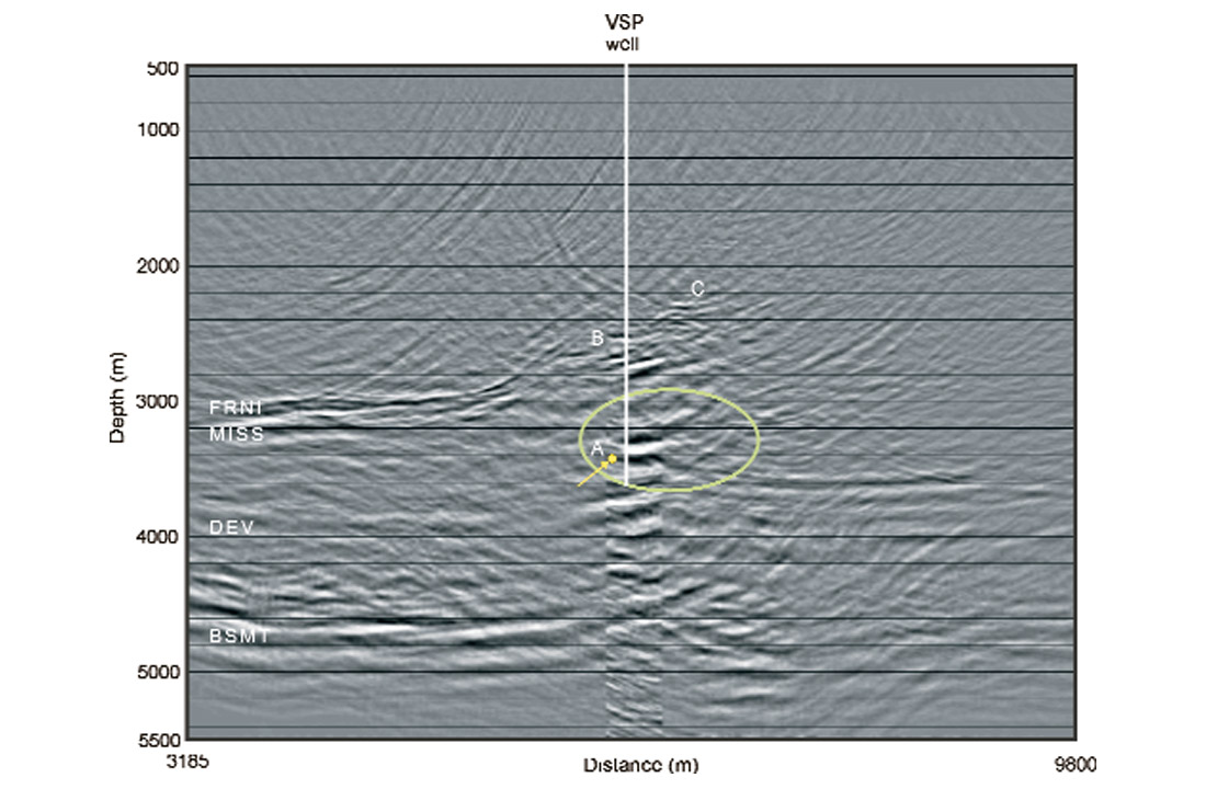
Figure 9c shows the integrated VSP and surface seismic depth-migrated image. Comparison of this image with Figure 9b shows the enhanced vertical resolution and increased structural detail at the location where the VSP has been summed in. In particular, the point marked by the arrow on Figure 9c can now be interpreted as the footwall cutoff of the thrust. If this interpretation is correct, it is expected that a thin layer of Fernie clastics should be encountered in the well as this depth, since they overlie the Palaeozoic carbonates.
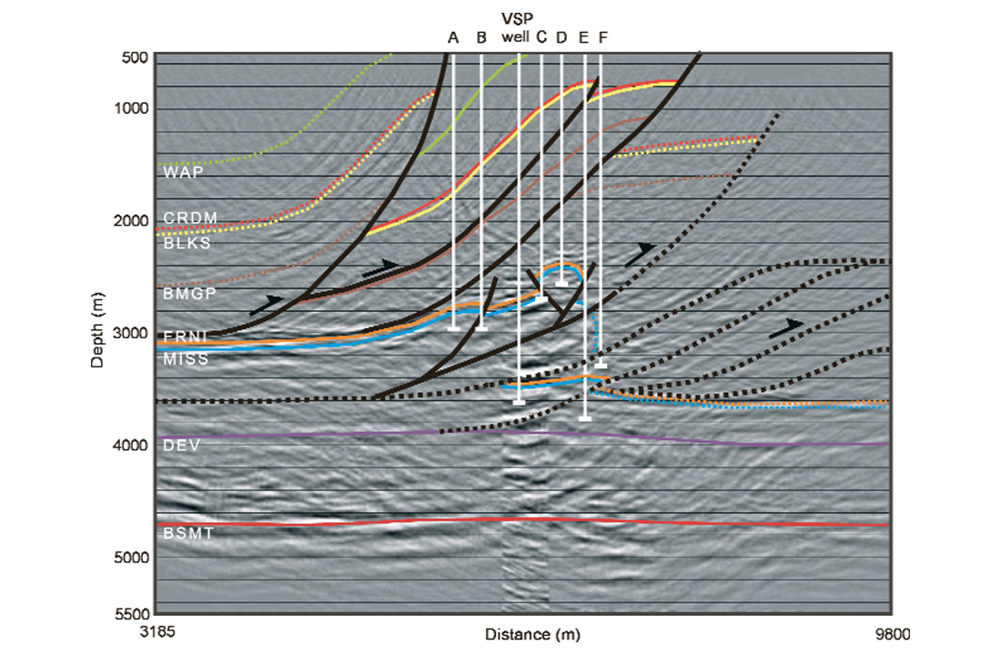
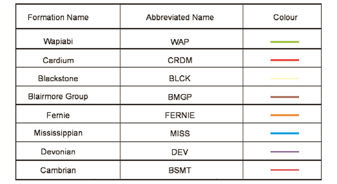
To finalise the interpretation, six nearby wells (marked by thin white lines and labelled A-F on Figure 9d) for which the formation tops were available were projected onto the surface seismic line to constrain the interpretation. The colours used in the interpretation, formation names and abbreviations used are given in Table 1. Figure 9d shows the final interpreted depth section. A layer of Fernie clastics about 60 m thick was encountered in the well at the expected depth of event A, with the other interpreted horizons also tying formation tops in the wells. This verifies that the integrated VSP and surface seismic anisotropic depth migration has imaged the exploration target at the correct location and with a clarity that could not be achieved with the conventional splicing approach.
Discussion
The new integrated approach to VSP and surface seismic depth migration has yielded a better overall image when compared to the surface seismic depth migration result or to the conventional VSP and surface seismic imaging approach, where the VSP image is simply spliced into the surface seismic depth section. The integrated VSP and surface seismic depth image contains higher vertical resolution, enhanced structural detail and also better lateral continuity of events. This led to optimum well ties and hence a more robust interpretation of the exploration target.
It is encouraging to note that a good integrated image was obtained with only 4 VSP shots and when the well, VSP shots and the surface seismic line were not in the same plane. It is therefore expected that the image would improve if more VSP data were available for migration and if the VSP and surface seismic data were acquired simultaneously and in the same plane, as has been illustrated in the numerical modelling example (Kirtland Grech et al., 2001a). This method may therefore prove to be especially useful now that combined 3D VSP and surface seismic acquisition is becoming more common.

Acknowledgements
We would like to thank Anderson Exploration Ltd. and PanCanadian Petroleum for giving us access to the VSP and surface seismic data. We also thank Alice Chapman, Placer Deguzman, Sam Gray and Al Petrella from Veritas GeoServices, Cam Grace from Anderson Exploration Ltd. and Andreas Bayer from Shell Canada (formerly at Anderson Exploration Ltd.) for their help and feedback. Financial support by the sponsors of the Fold-Fault Research Project and NSERC is also acknowledged.


Join the Conversation
Interested in starting, or contributing to a conversation about an article or issue of the RECORDER? Join our CSEG LinkedIn Group.
Share This Article