I am convinced significant volumes of hydrocarbons reside in naturally fractured reservoirs – particularly in fields abandoned because of improper testing and evaluation or because the wells did not intersect the fractures.1 Rules of thumb and naturally fractured reservoirs do not mix well. What appears to work in one might fail miserably in the next. Consequently, each naturally fractured reservoir (nfr) exploration play and each nfr under production must be considered as a research project by itself.
Geologic Aspects
Stearns2 defines a natural fracture as a macroscopic planar discontinuity that results from stresses that exceed the rupture strength of the rock. These natural fractures can have a positive, neutral, or negative effect on fluid flow.3 In my opinion, virtually all reservoirs contain at least some natural fractures. However, if the effect of these fractures on fluid flow is negligible, the reservoir can be treated, from a geologic and reservoir engineering perspective, as a “conventional” reservoir.
For reservoirs where the fractures have a positive or negative effect on fluid flow, it is of paramount importance to have knowledge of magnitude and direction of in-situ principal stresses; azimuth, dip, spacing, and aperture of fractures; matrix and fracture porosity, matrix and fracture permeability, and matrix and fracture water saturation. These data help in calculations of how the in-place hydrocarbons are distributed between matrix and fractures, and the flow capacity of the wells.
All naturally fractured reservoirs are not created equal. I am not sure if I read the previous sentence somewhere, if I heard it from somebody, or if I thought about it. Notwithstanding, I believe it is a very accurate statement, which means that we have to somehow classify and characterize the reservoir. This provides an important link between the geophysical, geological and engineering disciplines.
In addition to the fracture and matrix properties mentioned above, I recommend (1) classifying the reservoir from a geologic point of view keeping in mind that the fractures can be tectonic, regional or contractional, (2) evaluating the pore system, (3) quantifying the relative hydrocarbon storativity of matrix and fractures, and (4) getting a good idea with respect to the matrix/fracture interaction.
Geologic Classification
From a geologic point of view the fractures can be classified as being tectonic (fold and/or fault related), regional, contractional (diagenetic), and surface related1-3. Historically most hydrocarbon production has been obtained from tectonic fractures, followed by regional fractures and followed by contractional fractures. In general, surface related fractures are not important from the point of view of hydrocarbon production. When classifying fractures determine magnitude and direction of in-situ principal stresses; azimuth, dip, spacing, and if possible aperture of fractures.
Pore Classification
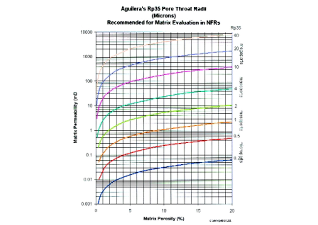
It is possible to make preliminary estimates of productive characteristics of common reservoir porosity types following a classification proposed by Coalson et al.4 In this classification, porosity classes are defined first by the geometry of the pores, and second by pore size. Included in the geometry are the following general pore categories: intergranular, intercrystalline, vuggy, and fracture. The combination of any of them can give origin to dual and even multi-porosity behavior.5
The pore size can be recognized from different techniques, including Winland4 r35 and Aguilera6 rp35 pore throat apertures. Included in the pore size are megaporosity (r35>10 microns), macroporosity (r35 between 2 and 10 microns), mesoporosity (r35 between 0.5 and 2 microns) and microporosity (r35 < 0.5 microns). Martin et al.7 have indicated that megaports are capable of flowing tens of thousands of barrels per day, macroports thousands of barrels per day, mesoports hundreds of barrels of oil per day, and microports tens of barrels per day. Figure 1 shows a graph for estimating values of Rp35 for the matrix in naturally fractured reservoirs. The graph follows the same format presented by Martin et al.7 using Winland’s equation.
The vast majority of papers and books on this subject discuss only fractures with apertures of a few microns. This is probably because of very poor core recovery from reservoirs containing fractures with much greater apertures. From laboratory work and experience it has been found that nut shells and plastic materials can stop circulation losses in fractures with apertures as large as 5000 microns. If in a given naturally fractured reservoir these materials cannot stop circulation losses the conclusion is reached that the apertures are bigger than 5000 microns at reservoir depth. In fact, secondary porosity apertures can actually reach cavern-size in some instances. Thus the generalized assumption that fractures cannot provide significant hydrocarbon storage is, in my opinion, not valid.
Storage Classification
From a storage point of view, fractured reservoirs can be classified8,9 as being of Type A, B or C. Many reservoirs that would otherwise be non-productive are commercial thanks to the presence of natural fractures.
In reservoirs of Type A, the bulk of the hydrocarbon storage is in the matrix porosity and a small amount of storage is in the fractures. The matrix typically has a very low permeability while the natural fractures tend to have a much larger permeability. But there are exceptions. For example, the matrix in the giant Saudi Arabian Ghawar reservoir has very large porosities and permeabilities.10 In this type of reservoir the fractures are a curse rather than a blessing because they facilitate unwanted water channeling. In this instance, efforts that integrate geologic information, 3D seismic data, and transient pressure analysis are directed at avoiding rather than intersecting the fractures.
In reservoirs of Type B approximately half the hydrocarbon storage is in the matrix and half is in the fractures. The matrix is tight and the fractures are much more permeable than the matrix.
In reservoirs of Type C all the hydrocarbon storage is in the fractures with no contribution from the matrix. Thus in this instance the fractures provide both the storage and the necessary permeability to achieve commercial production.
There are many reservoirs with fractures of tectonic origin where the primary porosity (matrix) tends to be occluded or has extremely low permeability and consequently does not contribute any hydrocarbon storage. In these cases, a large number of microfractures might be present that play the role of “matrix” porosity. This is due to the pervasiveness of tectonic fractures that exist from a macro scale to the grain size scale (they are very fractal). In this case the combination of micro and macrofractures can lead to dual porosity behavior.
Matrix/Fracture Interaction
Cores provide an excellent source of direct information for determining the kind of interaction that could be anticipated from fractures and matrix. Consider different possibilities:5
No Secondary Mineralization. Good luck or a teaser? When the natural fractures are open and have a negligible amount of secondary mineralization the hydrocarbons move from the matrix to the fractures in an unrestricted way.
How quickly the fluids move from matrix to fractures is controlled by the amount of pressure drop in the fractures, and matrix properties such as permeability, porosity and compressibility, viscosity of the fluid flowing, and fracture spacing or size of the matrix blocks. These kinds of fractures can provide very high initial fluid rates. The major problem with this type of fractures is that they might tend to close as the reservoir is depleted depending on the in-situ stresses, the initial reservoir pressure and the reduction in pressure within the fractures. In these cases, fractures are much more compressible than the host rock.
If the reservoir is initially overpressured the fracture closure can be very significant leading to small hydrocarbon recovery, big headaches and major financial losses.
If the reservoir is initially underpressured the fracture closure is not as significant because most of the closure at reservoir depth has already occurred. Ultimate fractional recoveries will be bigger than in the previous case.
Some Secondary Mineralization. I think good luck! When natural fractures have a certain amount of secondary mineralization the fluid flow from matrix to fractures is somewhat restricted. From the point of view of pressure behavior during well testing this can be visualized as a natural skin within the reservoir (not to be confused with mechanical skin around the wellbore routinely calculated). Partial mineralization is a blessing in disguise. In this case, the secondary minerals will act as a natural proppant agent and fracture closure will be significantly reduced (not completely stopped) even in overpressured reservoirs. This in turn will lead to higher ultimate recoveries. The fracture closure will be smaller in normally pressured reservoirs, and even smaller in underpressured reservoirs.
Complete Secondary Mineralization. Bad Luck!! Even if there is a lot of hydrocarbon within the reservoir, the ultimate recovery will be low. The mineralized fractures will compartmentalize the reservoir leading to very low ultimate recoveries.
Vuggy Fractures. They can have very large porosities that can reach 100% in some intervals and several darcies of permeability. Production can be several thousands of barrels per day if the vugs are connected (touching vugs). Vuggy fractures present the advantage that they do not close due to their rounded shape. Non-connected vugs provide non-effective porosity and permeability.
Engineering Aspects
Engineering aspects deal primarily with quantitative evaluation of naturally fractured reservoirs. This quantification links the geophysical, geologic and engineering disciplines. Some key goals are to estimate hydrocarbons-in-place, forecast production rates, and improve ultimate economic recoveries.
Characterization of the naturally fractured reservoir and engineering evaluations rely on direct and indirect sources of information.9 The determination of flow (or hydraulic) units11 is an important part of the characterization. Direct sources of information include cores, drill cuttings, downhole photographs and videos of the borehole. Indirect sources include outcrops, drilling history, mud log, conventional and specialized well logs, seismic information (preferentially 3D), well testing, inflatable packers, and production history.
Direct Sources of Information
They are very powerful because direct sources permit “seeing” the fractures categorically.
Cores. They represent the most important direct source of information. I recommend to always budget the necessary funds to core at least a few key wells. The successful study of a naturally fractured core must start at the well site.12,13 The laboratory must be selected carefully, followed by meetings with laboratory personnel, and an inspection of the facilities where the experiments will be conducted.14 Disruption of the fractured core must be minimized by using double-tube core barrels, which have successfully replaced rubber-sleeve coring methods. Disposable inner liners made of aluminum or fiberglass can provide good coring results because of their low friction coefficients and ability to prevent jamming.13 In case of some disruption the core must be properly fitted together and marked with scribe lines to make sure that it is correctly laid out in the laboratory for fracture analysis.12 The core should be preserved as best as possible, preferentially by wrapping it in plastic and placing it in ziplock bags. This precaution helps to prevent loss of reservoir fluids and/or core dehydration. In my opinion, oriented cores are advisable, although there is a trend in industry to orient cores with well log images (which are indirect sources of information).
A modern comprehensive analysis should include at least the following evaluations:14
- Fracture types description
- Grain density
- Petrophysical parameters m an n (m at simulated conditions of net overburden)
- Whole core porosity and permeability (at room conditions and some samples at simulated net overburden pressure)
- Routine core analysis
- Capillary pressures and relative permeabilities
- Wettability determination in a preserved core
- Imbibition recoveries if the rock proves to be water wet
- Mechanical testing (Poisson’s ratio, Young’ modulus, stress-strain analysis, matrix and fracture compressibility)
- Thin section analysis
- SEM (scanning electron microscopy) analysis
- Epoxy impregnation
- Spectrometric gamma ray and sonic velocity
- Solubility
- Non-destructive permeability determinations with a pressure decay profile permeameter
- Core scale pressure transient analysis15 and microsimulation of the fractured core.16
Drill Cuttings. Many times natural fractures may not be preserved in cuttings due to breakage along cuttings.
Consequently, the reservoir might be naturally fractured even if the cuttings do not show any fractures. However, there are exceptions. Hews17 has indicated that there are instances where cuttings can provide very useful information with respect to fractures. He indicates, and I had the opportunity to see it, that “with the samples wetted, internal textures including fractures and brecciation are more apparent. Dry samples are best to see any porosity that may be associated with a fracture plane.” Under these circumstances it is advisable to examine the cuttings thinking in terms of natural fractures. Crystals on the face of a fracture can be indicative of very effective fracture porosity. Thin sections from cuttings can also provide evidence of natural fractures. Cemented microfractures in thin sections can be extensions of larger open fractures.
Downhole Borehole Cameras. Photos and video tapes can provide direct information regarding many features penetrated by the borehole including natural fractures, faulting, bed boundaries, hole size and hole shape. There are video cameras that have been developed to examine vertical, slanted and horizontal wells. Air-drilled, low pressure reservoirs are prime candidates for application of video camera technology.18
Indirect Sources of Information
They include outcrops, drilling history, mud log, conventional and specialized well logs, seismic information (preferentially 3D), pressure data, inflatable packers, and production history.
Outcrops. There are essentially two schools of thought when it comes to the evaluation of outcrops. The first one indicates that19 “using outcrop data to characterize the fracture pattern of a reservoir is frustrated by the stress release which occurs as rocks come to the surface” and that “outcrop data is unsuitable for modelling reservoir fractures.” The second school of thought indicates that outcrops, when properly evaluated, can provide a significant amount of valuable information in exploration plays and during the development of a reservoir. I strongly recommend you to adhere to the second school of thought. A properly conducted outcrop study can provide information on spacing, connectivity and orientation of the fractures relative to the structure and stratigraphy. If you are going to drill a horizontal well, for example, the outcrop can help you determine the optimum orientation of the well to maximize productivity.20
Drilling History. It contributes valuable information regarding hydrocarbon shows, mud losses and penetration rates. Mud losses might be associated with natural fractures, vugs, underground caverns or induced fractures. Penetration rates can increase significantly while drilling all types of secondary porosity.
Well Logs. Logs are powerful indicators of natural fractures in some reservoirs. However, there is not a single log that is going to work all the time. I have used the following logs in the past, mostly from a qualitative point of view, to determine where the fractures are located: sonic amplitude, variable intensity, vertical seismic profiling, caliper, resistivity, Pe, borehole televiewer, dipmeter, spontaneous potential, density correction curve, borehole gravimeter, uranium index, temperature and noise logs. Details on these techniques are available in the literature of the various service companies.
Quantitative analysis can be conducted from image logs to determine fracture orientation, dip, spacing, connectivity, fracture aperture and permeability. My experience with images for determining fracture orientation, dip and spacing is good. However, my experience with calculated apertures and permeabilities is a mixed bag. I recommend assigning value to these parameters only from a relative point of view.
Quantitative analysis can also be conducted for estimating fracture porosity21 using dual porosity models, which are based on the observation that the porosity exponent of the fractures (mf) should be very close to 1.0. This is much smaller than the porosity exponent of the matrix (mb). The porosity exponent of the dual porosity system (matrix + fractures and/or connected vugs), m, varies between mf and mb. The smaller the degree of fracturing, the closer the value of m to mb. The larger the degree of fracturing, the closer the value of m to mf. In the case of dual porosity systems made out of matrix and non-connected (non-touching) vugs, the value of m is larger than mb. Care must be exercised when using dual porosity models, as the incorrect scaling of the matrix porosity can lead to errors in the calculation of water saturation.21
Seismic Information. Significant advances have been achieved in 3D seismic technology that allow in some cases determination of fracture orientation, anisotropy and fracture density22 and the type of fluid that could be present in the reservoir. Under favorable conditions, this can be estimated using AVO (amplitude vs. offset) and AVAZ (amplitude vs. azimuth) interpretation techniques.
Well Testing. This in an area that has also seen significant advances in the precision of the tools and the interpretation software packages. Modern formation testers can provide vertical information that cannot be detected by a standard test. Multiple probes can show the presence or lack of vertical interference in a wellbore. Automatic type curve matching is powerful but dangerous. To avoid fiascos with automatic matching, it is important to make sure that the engineer is always on top of the interpretation. Numerical 2D well testing models using unstructured Voronoi grids (PEBI) provide a significant and necessary extension to the more conventional Cartesian, semilogarithmic and log-log derivative crossplots.
A properly designed and supervised test can provide valuable information including fracture permeability, fracture porosity, and fracture spacing in addition to usually estimated parameters such as skin, radius of investigation, extrapolated pressures, etc.
Production History. If from cores the permeability of a formation is 0.1 md, and the well produces 1,000 bopd, it can be inferred that the rate is the result of some type of secondary porosity, including fractures. Premature water or gas breakthrough in secondary recovery projects can also indicate the presence and strike of natural fractures. To avoid these unpleasant surprises, it is advisable to perform pressure interference tests early in the life of the reservoir.
Recovery Factors and Reserves
The optimum way of forecasting performance and recovery is utilizing a reservoir simulator as long as the reservoir characterization and the quality of the pressure and production data is good. Based on my experience, it is reasonable to forecast twice the time of available history. For example, if there are two years of good production and pressure data, it is reasonable to forecast four years of production.
Compressibility
If the reservoir is composed by matrix and fractures, the compressibility of the fractures is bigger than the compressibility of the matrix. The relative difference between the two compressibilities depends5 on various factors including the amount of secondary mineralization within the fractures, the orientation of the fractures and in-situ stresses, and if the reservoir is over-pressured, normally pressured, or under-pressured.
Closing of the fractures once the reservoir goes on production can be very significant in over-pressured reservoirs. This can lead to huge declines in production rates. Fracture closure in underpressured reservoirs is less significant as most of the closure has already occurred.
In a dual porosity system made out of macro and microfractures (and without any primary porosity) the macrofractures play the role of “fractures” and the microfractures play the role of “matrix.” In this case, there are instances in which the microfractures (matrix) can be more compressible than the macrofractures (fractures). In other instances both compressibilities can be of the same order of magnitude.
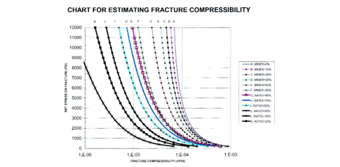
Whenever possible, it is advisable to determine compressibilities in the laboratory using rocks from our own reservoir. If this is not available we have to rely on empirical correlations. Figure 2 shows a correlation5 that I have used with reasonable success for a number years.
Ranges of Recovery
Each naturally fractured reservoir should be considered as a research project by itself. As such it has to be studied carefully to estimate recoveries. It is wise to remember that naturally fractured reservoirs and rules of thumb do not mix well. What appears to work in one reservoir might fail miserably in the next.
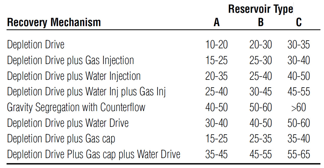
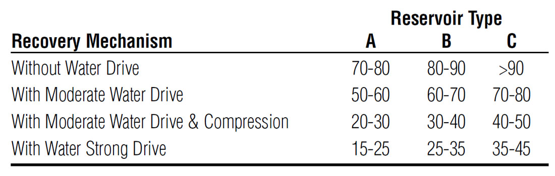
Tables 1 and 2 show some ranges of recoveries5,23 based on my experience working with naturally fracture reservoirs worldwide for about 30 years. These oil and gas recovery estimates are presented for different recovery mechanisms and different types of fractured reservoirs. They are no panaceas. Use them carefully and only as order of magnitude indicators. There is no substitute for a detailed study.
Although in general, percent hydrocarbon recoveries from Type C reservoirs are larger than for Types A and B, the engineer has to be careful because usually the amount of hydrocarbon-inplace in Type C reservoirs is smaller.
Reserves
An excellent source24 regarding proved, probable and possible oil and gas reserves is the Petroleum Society of CIM Monograph No. 1 published in 1994. When it comes to naturally fractured reservoirs, I recommend using statistical procedures to quantify the uncertainty associated with hydrocarbons-in-place and reserves.
Most naturally fractured reservoirs I am familiar with are characterized by low matrix porosities (less than 10%) and low matrix permeabilities (less than 1 md). For these reservoir characteristics it is difficult to place a reasonable certainty of volumetric estimates of original hydrocarbons-in-place and reserves. As a consequence, I recommend placing reserves from volumetric estimates in the possible category. For matrix porosities larger than 10% and matrix permeabilities larger than 1 md the reserves can be moved to the probable category.
Early material balance calculations can provide estimates of probable reserves. As the cumulative production increases and with good quality pressure data (long flow and long shut-in times) the material balance reserves can be moved into the proved category.
I place production decline estimates from short history in an unproved category. Long production history leads to reasonable estimates of proved oil reserves. I do not recommend decline curves for estimating proved reserves of gas reservoirs unless the wells are at a late stage of production where a constant surface compression pressure is being utilized.
Beware of water influx in naturally fractured gas reservoirs. A well might be producing extremely well. But it is not unusual to see that the gas rate goes to nothing once water reaches the wellbore.
Reservoir simulation, although imperfect, is the tool that in my opinion provides the most reliable source of information for estimating recoveries and proved reserves. A significant amount of high quality data is required. The longer the production history the more reliable are the forecasted results.
Early in the life of the reservoir when production history is short or non-existent, proved reserves can be estimated from well designed, well supervised interference tests using high precision pressure gauges. The larger the number of wells involved in the test the better. In addition to providing reserves, the test will give very useful information regarding anisotropy.
If the objective is estimating reserves by investigating both matrix and fractures, I do not recommend pulse tests with short flow and buildup periods. Long continuous flow times during the interference test are required to properly investigate both matrix and fractures.
If there is only one well in the naturally fractured reservoir, I recommend a long flow period following the collection of a good initial pressure. An estimate of the radius of investigation leads to a volumetric estimate of hydrocarbons-in-place within the investigated area. This requires a reasonable estimate of net pay, matrix and fracture porosity, and matrix and fracture hydrocarbon saturation.
A Review — and a Look Ahead
Since my early days working with naturally fractured reservoirs in the early seventies, I have seen extraordinary advances in the geophysical, geological and engineering fields. These advances have led to improved estimates of recoveries and reserves. These improvements will continue.
Over the next few years, I anticipate significant improvements in seismic technology to better characterize anisotropy of naturally fractured reservoirs.
There will be advances in the evaluation of whole cores and the uncertainty associated with estimates of fracture compressibility will be reduced.
Imaging logs will continue improving and this will lead to more reasonable estimates of fracture parameters.
More, better and more realistic well testing and reservoir simulation models will be developed. Simulation grids will be improved. Unstructured Voronoi (PEBI) grids in 3D will become standard features of well testing packages. Software “friendliness” will be a big part of these models. Coupled fluid flow and rock mechanics simulators that take into account normal and shear stresses will become functional.
Hydrocarbon recoveries will continue increasing as more deviated and horizontal wells are drilled underbalance to properly intersect (or if desired avoid) vertical and high inclination natural fractures.


Join the Conversation
Interested in starting, or contributing to a conversation about an article or issue of the RECORDER? Join our CSEG LinkedIn Group.
Share This Article