In 2002 Input/Output commercialized its full-wave digital sensor system known as VectorSeis™. Since the initiation of field testing in 1999 more than 65 surveys have been acquired worldwide with these MEMS (micro electro-mechanical systems) based sensors. Of these, 38 have been commercial seismic surveys in Western Canada. Observations by interpretation staff indicate that the majority of these surveys have exhibited improved P-wave data. This article will postulate that this improvement in the P-wave is due at least in part to the vector fidelity improvements inherent in the VectorSeis design.
Full-wave recording entails using a multicomponent sensor to accurately represent the three dimensional particle motion of the seismic signal. Recent advances in sensor technology means this can now be achieved in a direct digital manner thereby minimizing any possibility of signal corruption. Classical P-wave recording preserves only one axis, the vertical component of the wavefield. Having discarded the others, it is often difficult to solve simple problems later. Other aspects of the wavefield (i.e. shear waves) will have tremendous value as tools continue to develop.
During the design of the VectorSeis sensor system the requirements for good vector fidelity were studied closely. With time it became clear that there are four key design elements required to achieve a high degree of vector fidelity:
1. Sensitivity:
- Tested by exciting a sensor in its working axis and monitoring the output.
- Axis to axis differences in sensor sensitivity must be minimal, -45dB or better.
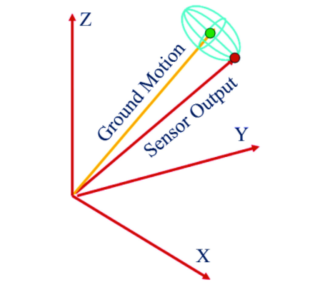
- Errors will preferentially distort vector magnitude and direction (Fig 1).
2. Cross axis rejection:
- Tested by exciting individual sensors and systems both in the working axis and orthogonal to that axis and measuring the output.
- The ratio must be very low, -60 to -80dB for individual sensor elements, -45dB or better for system of 3 sensors.
- Poor cross-axis response in a sensor will create output where none should exist.
3. Orthogonality:
- Axes must be highly orthogonal to one another.
- Errors in orthogonality will distort vector direction and magnitude (Fig 1).
4. Tilt at Deployment
- If a conventional sensor is deployed with an unknown tilt, it is difficult to determine the vertical component with any certainty. Hence the need to level them during deployment (a labour intensive task).
- By employing a MEMS sensor which is referenced to gravity all tilt ambiguity is removed and field deployment is dramatically simplified.
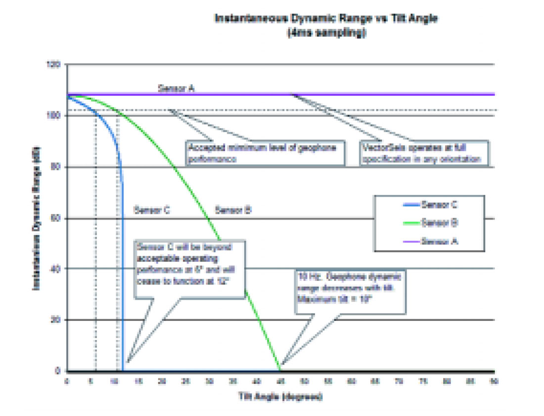
- Such a system only works effectively if the sensor is force balanced against gravity (Fig 2).
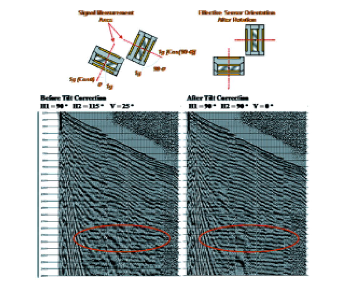
These parameters combine to ensure that when the vertical data are extracted from the wavefield recorded by a digital full-wave sensor, it is done with a minimum of distortion (Fig. 3).
Historically full-wave sensor systems either lacked any high degree of vector fidelity or were operationally inefficient to deploy. Recent advances in MEMS based sensor technology have achieved full-wave sensor systems with excellent vector fidelity in a package that simplifies deployment. Because of these advances we are recording P-wave data of unprecedented quality. This is achieved by acquiring the full wave signal with the sensor in any arbitrary orientation, the sensor automatically reports its inclination relative to the earth’s gravitational field. Data are projected into a conventional Cartesian system during in-field pre-processing, using gravity as the reference. The extracted vertical component is a far more precise measure than conventional techniques (Fig. 3).
It is worthwhile taking the time to question the assumption most geophysicists make whenever they use data recorded using classical techniques — that their P-waves are propagating vertically. This is probably a reasonable assumption at near zero offsets. As offsets become larger emergent angles begin to grow. Thanks to the velocity contrast in the overburden and Snell’s law it may still be a valid assumption. At far offsets it is possible but it is by no means a requirement. If the wavefield is emerging in a non vertical manner then the classical P-wave sensor system will, by definition, only record the cosine of the energy. In addition, other source related wave types can have significant expression in the vertical domain. These would include phenomena such as:
- Ground roll
- Air blast
- Shear waves
- Back scattered energy
Because the full particle motion has been ignored during classical P-wave recording, geophysicists often resort to elaborate signal processing techniques in an attempt to improve the S/N ratio of their data. These techniques are often less than satisfactory because too much information has been lost in the conversion from full-wave to P-wave only.
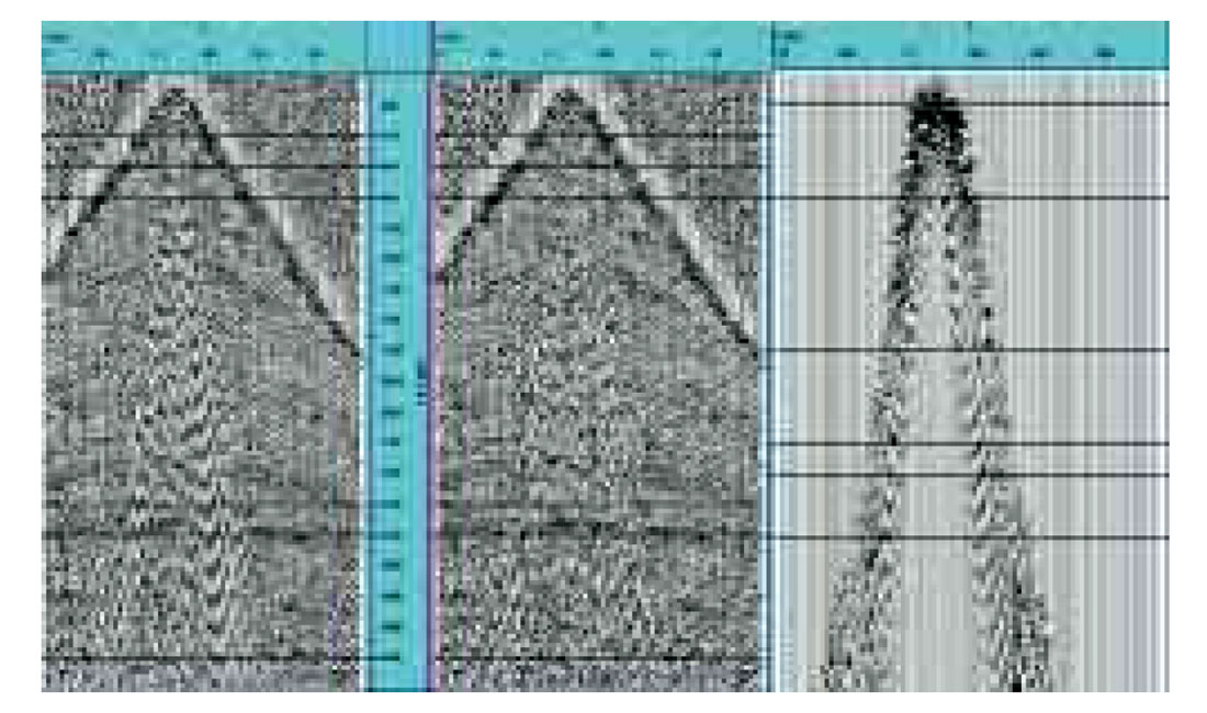
Full-wave recording offers new possibilities for suppressing these less desirable wave forms. Using advanced techniques based on characterizing signal and noise in multiple planes, algorithms such as adaptive vector filtering are demonstrating impressive results (Fig. 4). They are currently being used to suppress ground roll on P-P and P-S data, and also have application in suppressing undesirable body waves (i.e. non vertical P-P and P-S waves which leak into the orthogonal projection thereby lowering the S/N). Future algorithms will explore the potential of more sophisticated techniques such as polarization filters.
Of course, these techniques rely upon the sensor system having not compromised the vector fidelity of the wavefield. In retrospect, a number of the early disappointments in multicomponent acquisition and processing can be traced back to poor vector fidelity in the sensor systems.
Looking into the future, full-wave digital recording offers several unique opportunities to improve on classical P-wave data. Early examples are very positive. Vector fidelity is proving to be the important element in overall data quality. A number of unique tools have already been developed and more are expected. As processing and interpretation tools become available for shear waves, they will make an increasing impact on seismic solutions.


Join the Conversation
Interested in starting, or contributing to a conversation about an article or issue of the RECORDER? Join our CSEG LinkedIn Group.
Share This Article