The oil and gas industry is currently undergoing an extended period of instability. Technology can be leveraged to improve these difficult circumstances. The challenge is to develop ground-breaking technologies that help manage new projects more efficiently. At the same time, there is a tremendous need for technology to ensure a better understanding of the reservoir, for instance, in producing more accurate pictures of the subsurface, and to resolve fracture networks. Also, efforts are spent to intensify seismic monitoring, both in marine and land contexts, despite the current economic downturn.
Usage of technology has a cost, and it may exceed industrial budgets. Industry should balance long-term investments in production optimization and field development, while expending serious efforts to improve monitoring to make environmentally safer hydrocarbon extraction. In this work we shortly review some examples of enhanced seismic techniques that are either emerging or have already been proven to better monitor physical properties, mainly in land hydrocarbon reservoirs. References are made numerically and listed at the end of the paper.
We also discuss optimal monitoring strategies of the hydraulic fracturing technique for environmentally safer hydrocarbon production ([3]). Alongside concrete advancements, we critically underline some major limitations, as well. Finally, a discussion about the real impact of such enhancements will be presented. Technological innovations, and their potential, need to be critically evaluated.
Seismic monitoring
More and more, industry is considering seismic monitoring as a valid decision-making tool for functional reservoir management in the long term, and for a safer extraction. Figure 1 shows, schematically, the basic elements characteristic of any seismic monitoring (for both land and marine contexts). Equipment, cost, challenges, target, and output are key factors.
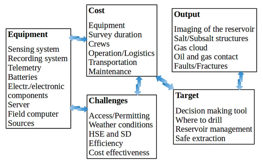
As contractors, service companies are normally committed to the oil and gas industry to conduct seismic monitoring using specific equipment, consisting of sensing, acquisition, and transmission systems.
The sensing system refers to the real sensors, which are deployed in the field. The acquisition system comprises the sources (e.g., land vibrators).
The transmission system, known as ‘telemetry’, refers to the way of transmitting the data to the center station. Different types of telemetry are now available to seismic operators, from the classical cabled solutions, to transmission based on radio, cellular phones, or optical fiber. GPS receivers can be built directly into sensing equipment, allowing for space-bridge communications among sensors and the center station.
Sensing and transmission in optical fiber represents one of the most recent innovative technological developments in seismic monitoring, e.g., in marine seismic (see [1]).
Advances in seismic data acquisition have led to a huge increase in exploration and production efficiency, enabling more data to be collected more quickly and reliably. As an expected impact, images of the subsurface geological structures ([7]) are greatly improved. Cost effectiveness is an important factor which operators have had to take into account, as well as logistical aspects. Crews manually deploy the acquisition systems, and can operate sometimes in very challenging environments (e.g., in Arctic areas) or even in sensitive areas (e.g., war zones); consequently, health and safety conditions (HSE: Health, Safety and Environment) are of great concern. Permitting and access to the field can also present a challenge, especially if monitoring leaves a strong environmental footprint. In addition, the monitoring system has to be proven to follow the criteria of Sustainable Development (SD).
Classical monitoring in land hydrocarbon reservoirs
Seismic techniques used in the monitoring of land hydrocarbon reservoirs mainly make use of cabled acquisition systems, via one of three types of installations: surface arrays, buried arrays and down-hole arrays.
Surface arrays are confined to the site topography, while down-hole and buried arrays require drilling. With down-hole arrays, sensors can be deployed near the depth of the reservoir or straddling the formation target (see Figure 9 in ([2]). Buried arrays require only shallow drill holes, at variable depth, typically between 10 and 100 m.
Geophones with one (1C) or three (3C) components, constitute the most preferred and trusted sensing equipment. They are usually planted by foot in the ground, in lines equally spaced and in geometric arrays. Classical seismic acquisition systems use analog cables to connect multiple external sensors (usually geophones) to an acquisition unit ([10]). Analog data are then amplified, filtered, and digitized in the unit into specific recording digital channels. Additionally, an external cable and (usually) a series of connectors are needed to transfer the analog signals from the external sensors to the acquisition unit. For land seismic, six or more geophones in a string constitute a sensor array. In most of the cabled systems, digitized data are subsequently transmitted through other cables to a central recorder ([6]).
Operators still feel comfortable with the ‘historically trusted’ cabled telemetry form, since these cables enable them to retrieve data in near real-time, through high-speed transmission protocols. In addition, the imaging quality of the reservoir, which is reproduced through data processing recorded by geophones, is deemed to appropriately satisfy the need of monitoring. Classical acquisition comes with disadvantages, as well. Firstly, cabled systems often require crews to spend the better part of a day troubleshooting the cables/connectors and the sensors to resolve varied issues of electrical nature, including leakage and continuity problems. The field components can be easily damaged by different sources, both natural and cultural, exacerbating the maintenance requirements. To make things worse, in terms of HSE and SD protocols, cabled acquisition increases the risk of injury to crews, since cables and equipment (around 20 kg) need to be carried for long distances, in any weather conditions. Lastly, this operation can leave a considerable environmental footprint. Moreover, under the premise of an ever-increasing number of recording channels (up to 30,000 channels), it is just unmanageable to deploy such a number of sensors using cables ([9]). There is, therefore, an increasing need for a new generation of cost-effective seismic acquisition systems, that is capable of handling a high number of recording channels, is easily manageable, and that can improve the imaging quality of the monitoring output.
Enhancements in reservoir technology
Part of the answer to the needs of seismic operators is filled by technological enhancements in reservoir technology: cable-free autonomous nodal systems, broadband measurements, and permanent buried arrays.
Cable-free autonomous nodal systems
Enhancements in technology are, very recently, making seismic acquisition shift towards the next generation: cable-free systems. A single cable-free acquisition point is called a ‘node’, and an ensemble of nodes constitutes a ‘nodal system’. Amplification, filtering, and digitization take place directly in each node. Autonomous nodes have the advantage of providing far greater flexibility in deploying large numbers of receivers, even in urban and environmentally sensitive areas, yielding very efficient exploration or high-density production surveys. One of their major advantages is the minimum environmental impact, and reduced crews ([4]). In addition, the lack of any cables connected to the nodal units significantly decreases wind and cultural noise ([10]), thereby increasing the system’s Signal-to-Noise Ratio (SNR). Seismic data are stored internally in each node on flash memory drives. There are no physical connections or communications between nodes, nor with any other equipment or the central unit. They require no external connections, except for a GPS (Global Positioning System) link for timing, and a battery for power ([7]). This type of telemetry is referred to as ‘blind local recording’, or simply data storage. Besides blind systems, there exist also semi-blind systems, which store the data in an internal memory system, yet with enough communication capability to provide some real-time quality control (QC) and sometimes the delivery of partial seismic records to a central unit.
Blind recording systems have great flexibility, therefore improving monitoring; however, some concerns can be discerned. The first is related to the need of collecting and transcribing the data ([4]). This procedure could be exhaustive and time-consuming. More than anything, some users are uncomfortable with this time delay. From the operator’s point of view, blind systems require waiting to see how the data look. On the other hand, contractors would like to be informed right away if there is a problem, in order to adjust the survey as soon as possible, rather than repeat a few weeks of expensive monitoring.
Besides blind local recording systems, there exist methods for active telemetering of data, such as radio transmission. Telemetered Radio Frequency (RF) systems require that each node (or remote acquisition unit) acquires, digitizes, filters, and ultimately transmits the data to the central recorder, where the data are placed onto a storage medium.
Nodal systems with RF telemetry have been very recently deployed during hydraulic fracturing microseismic monitoring (e.g., [5]). Seismic surveying now makes use of one of two RF telemetry modes: real-time or reasonable-time ([9]). In real-time, all data acquired during one sample interval must be transmitted from the nodes to the central recorder before the next sample interval is acquired. Reasonable-time telemetry sends full acquisition records back to the central recorder, while the nodes are acquiring data from the next record. This kind of transmission system is the most preferred by RF telemetry, and allows additional time to transmit the acquired data.
There are some limitations to the potential of reasonable-time telemetry. This method is actually pushing the limits of current RF technology, and concerns have been raised that both the RF telemetry modes are rapidly approaching their limits as channel count escalates ([9]). A solution to this issue could indeed be addressed by the usage of autonomous surface nodes.
Some general issues of monitoring with nodes can be readily discerned, such as the security of the equipment. Autonomous nodes could be easily extracted from the soil and stolen. Each node needs a battery for functioning, and power consumption is always an issue. Travel for recharging the batteries could also leave a significant environmental footprint. It appears, therefore, that the elimination of cables nevertheless introduces other technical problems.
Broadband measurements
If, in seismological observatory practice, the concept of broadband refers more to the instrumental characteristics (e.g., velocimeters), in exploration seismic the term “broadband” denotes more the real capability to provide seismic imaging results, and in particular, lower frequency. This target can be achieved essentially with the introduction of new ways of sensing, acquiring, and processing seismic data, together with broader frequency sources.
In the advent of a new generation of digital seismic sensing, the following types of broadband sensors are listed: Geophone Accelerometers (GAC), Micro Electro Mechanical Systems (MEMS), and Optical Sensing (OS).
Classical geophones typically measure the ground motion as velocimeters, in a frequency band above their specific natural or resonance frequency, usually 10 Hz. However, below the resonance frequency the geophone acts effectively as an accelerometer. This characteristic has been exploited by Schlumberger to develop the GAC. Coil-based GACs are typically insensitive to tilt, and their amplitude response in the acceleration domain is linear at lower frequency (at velocity response down to the eigenfrequency, e.g., 2 Hz). However, the phase response still remains variable ([14]).
The last step towards full digital recording was made in the early 2000s with the launch of a new generation of digital seismic sensors based on MEMS (Micro Electro Mechanical Systems) accelerometers with the real potential to replace analog geophones ([17]). The MEMS sensors behave as broadband accelerometers. There are two models, basically classified as VectorSeis (manufactured by Sercel) and DSU (manufactured by Inova). Examples can be found in [13]. At the basic fabrication design, MEMS have two principal construction components, namely a silicon micro-machined accelerometer with a small inertial mass, suspended by miniature springs, and a custom designed, mixed-signal, Application- Specific Integrated Circuit ([11]).
The advantage of the accelerometers based on MEMS is that they act like capacitors, flattening both the amplitude and the phase response over a wide frequency range from 0 Hz (DC) to up to 800 Hz. The capability to sense DC is not exploitable for seismic recording, rather to detect the gravity vector used as a reference for calibration and tilt corrections ([15]).
Broadband instrumentation is currently applied in land seismic. Examples of improvements in monitoring can be found in e.g., [12] in comparison to geophones. However, the overall benefits of a broadband acquisition in frequency content and accurate amplitude appears in imaging only after data processing.
Finally, broadband technology has been recently implemented in optical sensing systems. Particularly in these times, the oil and gas industry is experiencing an inflection toward fiber-optic sensing ([1]), due to low cost and high reliability in measurements.
Permanent buried arrays
This seismic technique requires shallow drill holes only, and sensors are typically deployed between 10 m and 100 m in depth. A characteristic of this technique is that sensors are cemented in, and can monitor throughout the whole lifetime of the field.
Operators can choose the sensing equipment of buried arrays, and between classical cabled geophones or digital sensors. The number of shallow buried sensors depends on local conditions and the spatial extent of the area to be monitored. Typically, one sensor is located in each well, and the digitization system could be placed in a corresponding area on the surface (see [8], Figure 6).
Buried arrays have the capability to record the seismic wavefield with wider azimuth, in high fold and larger aperture geometry in comparison to down-hole monitoring. Buried configurations have recently proved to dramatically advance the quality of recorded seismic data, in comparison to surface and down-hole. One of the main reasons is noise reduction, especially the ambient noise caused by cultural or anthropic activity (up to 15 dB, see [16]), and the low-frequency near-surface coherent noise. An ulterior strength of buried arrays is flexibility and versatility, as well as the ability to monitor large areas repeatedly, containing multiple well-pads, by making use of the same equipment. This leads to more strategic field planning and development ([16]). Recently, operators have been offered the possibility to deploy shallow, permanently buried configurations, as a cost-effective tool to monitor hydraulic fracturing and hydrocarbon production effects. Examples can be found in [8].
A potential limitation can be discerned: drilling many wells, carrying out equipment and cementing in place leaves a strong environmental footprint.
Hydraulic fracturing monitoring perspective
We focus now on hydraulic fracturing (HF), and address the monitoring strategies for that context. Two main environmental concerns can be identified: the risk of stray gas migration towards sensitive receptors (e.g., aquifers) and uncontrolled induced seismicity.
Seismic monitoring systems during hydraulic stimulations measure brittle failures of the stressed crust due to a high-pressure fluid injection procedure. Such failures cause microseismic events, which carry information relating to fluid movements in the reservoir area. Microseismicity allows drilling engineers to track fracking operations, optimize production, and control potential geohazards.
Towards near-real time monitoring
[5] discussed some features of monitoring during HF treatment. Firstly, the area where to frack. A developed field could consist of roads, drill sites, rivers, and scattered equipment (e.g., trucks, facilities, etc.). Secondly, the duration of the treatment: it is typically short (e.g., maximum one week). These elements do not point to the usage of cabled acquisition systems, especially in the presence of natural or industrial obstacles.
As specified previously, autonomous blind systems record data using built-in memory, but this information can only be available after the frac job is completed. However, drilling engineers would like to receive the information in near-real-time. Indeed, the trend in industry is projected towards real-time wireless solutions capable of delivering information, e.g., the microseismicity, within minutes of the event, or soon enough to adjust the treatment if environmental concerns occur. Information about induced hypocenter location and size is finally passed back to the rig, which is pumping the fluids. Tracking the fracturing fluids is of primary importance, especially when it starts moving away from the target area.
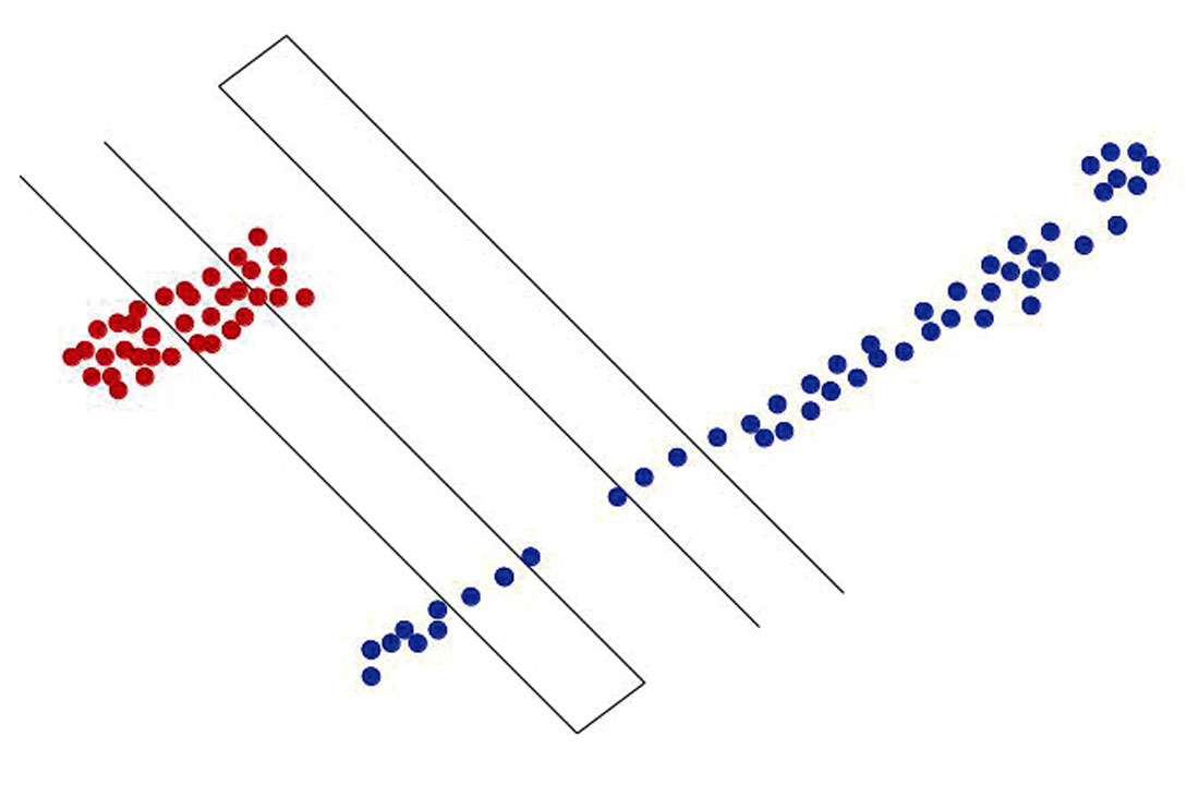
A schematic example is shown in Figure 2, where the induced microseismicity (events in red) is, on one hand, clearly located inside the reservoir target. On the other hand, fluid likely escaped through a buried unseen fault (events in blue). In similar cases, for effectiveness and safety, the treatment protocol can be modified. If a casing failure occurs, immediate feedback can be provided to avoid polluting an aquifer.
If the induced microseismic events start developing into larger events enough to be felt by the population in the area the pumping can be reduced.
The need for real-time monitoring is clearly expressed by local jurisdiction all around the world with regulations that insist on real-time monitoring before, during, and after hydraulic fracturing ([5]).
[5] proposed cable-less systems with radio relay transmission. They present advantages and limitations of systems based on radio transmission, without analyzing the capability in event detection.
The main advantage is the capability for operators to retrieve microseismic information in a fast and effective way (within a couple of seconds). Also, these systems meet the need of a massively high digital channel count, and being autonomous nodes, they leave a minimal environmental impact, with much lower HSE exposure.
In terms of limitations, radio transmission presents a first issue, namely the available bandwidth. When distributing thousands of geophones in an area, a large bandwidth is needed. The use of a 2.4 GHz band could be suggested, due to the advantage of being license-free in much of the world. However, this band has limited range, except in permanent installations with towers, parabolic antennas and line-of-sight clearance. Such radio devices are equipped with short, non-directional antennae close to the ground, in an area with vegetation and rolling hills. However, such devices can only communicate a few hundred meters, especially at a low-enough power that practical batteries can keep the system up for the duration of the survey or frac. Therefore, [5] indicate the ideal solution in designing individual station units to not only collect data, but to act as a radio relay. A remote acquisition unit (station) collects data and transmits it to the next station in the cross line. Each station then receives the data, adds its own data, and sends it further down toward the backhaul or doghouse receiver.
Discussion
After detailing enhancements in seismic techniques, it would be natural to ask oneself to which degree the oil and gas industry is really affected. Let us consider for instance the case of the broadband revolution. Is the industry really fascinated by this novel broadband technology, and ready to say farewell to conventional geophones? [17] tried to make the point of the impact of MEMS in industry. They stated that these digital sensors have established a foothold, and indeed even become a reference for a number of different applications, but this has not yet lived up to the expectations of the seismic industry. This lack of full development of the digital sensors may reflect a reluctance of the oil and gas industry to adopt new protocols, or opening up to new ideas.
One of the biggest concerns among the enhancements in the described seismic techniques is data quality. Does the technology really accompany improvements in signal quality? For all of the described acquisition systems, the situation might still be untidy. Industry needs time to properly address the question. Above all else, claimed technological enhancements, when they come, have to be approached with a critical eye, and supported by concrete improvements in data quality.
Conclusions
In the current period for the oil and gas industry, innovation in technology drives a new phase in monitoring of hydrocarbon reservoirs, especially what concerns the seismic sector. A variety of technological innovations are now available for seismic monitoring. Operators have the option of giving away cumbersome and rugged classical analog cabled solutions with strings of geophones. Digital autonomous nodal systems could represent a potentially valid alternative, since they have proved to monitor in a more efficient way, especially with much lower HSE exposure for crews and less environmental impact. Nevertheless, the elimination of cables introduces problems of a technical nature, since each node requires a battery. Operators can also test the capability of acquiring and measuring in broadband, namely by extending the low-frequency spectrum to visualize deeper sections of the reservoir.
Technology can also now give operators more confidence that their industrial operations can be conducted more safely, environmentally. For instance, shallow permanent buried arrays have become an efficient way for monitoring induced microseismicity during hydraulic fracturing, as well as optimizing recovery and field development. It also appears clear that, for guaranteeing safer extraction, near-real time monitoring solutions, for instance based on radio transmissions, are needed to avoid geohazard. This need has been specified by regulators all around the world.
Finally, it appears that the oil and gas industry is fascinated by new technologies, while at the same time there is some reluctance to change current proven procedures. Above all else, enhancement in seismic technology needs to be associated with concrete improvements in data quality, in resolution, and in the quality of the seismic images.

Acknowledgements
The authors thank the FracRisk community for constructive comments and suggestions, as well as H. Granser (OMV) and the geophysics team of the Department of Meteorology and Geophysics. This project has received funding from the European Union’s Horizon 2020 research and innovation programme under grant agreement No. 636811.


Join the Conversation
Interested in starting, or contributing to a conversation about an article or issue of the RECORDER? Join our CSEG LinkedIn Group.
Share This Article