The Jurassic Louann salt has played a dominant role in influencing the structural and depositional history of the East Texas Basin. Petroleum traps within the basin exhibit structural and stratigraphic elements influenced by salt tectonics, particularly during the Jurassic and Cretaceous periods. Petroleum reservoirs in East Texas Basin include the Jurassic Cotton Valley Lime, and Cretaceous Pettet, James, and Rodessa limestones, and the Woodbine sandstone.
Salt withdrawal basins, developed during the Early Cretaceous in response to salt movement and dissolution processes, are characterized by the presence of an expanded section of Lower Cretaceous marine and deltaic sedimentary rocks. Recognition of ring faults associated with the evolution of these salt-withdrawal basins had gone undetected until recent Coherence Cube™ processing of a spec 3-D seismic survey acquired in 1997 following oil industry interest in exploring for Jurassic Cotton Valley Lime reef production in Henderson and Anderson Counties, Texas.
Discovery of Early Cretaceous-age ring faults brings new perspectives to development and exploration drilling in the mature petroleum province of East Texas. The structural style of the high-angle ring faults creates a multitude of possible fault traps in a previously unattractive synclinal structural setting, including the possibility that the closely-spaced ring faults may host fractured reservoir plays. Mapping of ring faults, aided by Coherence Cube processing, may lead to future petroleum discoveries in the East Texas Basin.
Geological Setting
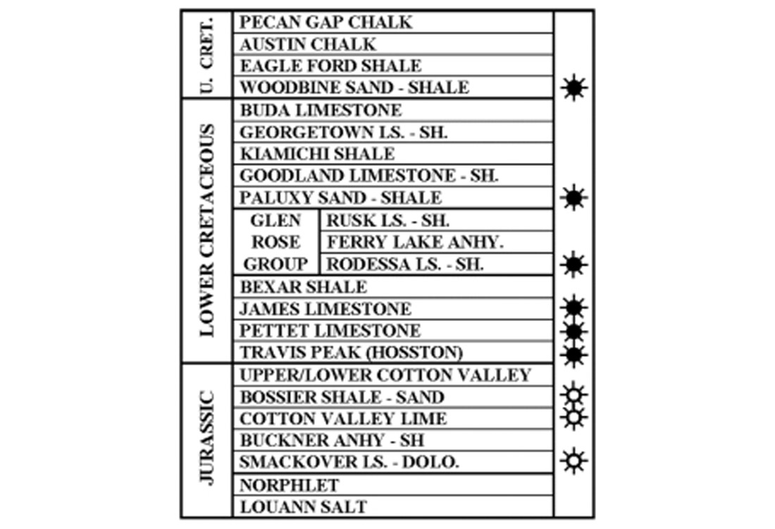
The Fairway 3-D seismic survey is located in the East Texas basin, a mature, major hydrocarbon province in northeastern Texas (Figure 1). The basin formed during the Late Triassic-Early Jurassic and contains over 20,000 ft (6,100 m) of mostly Jurassic and Cretaceous rocks (Figure 2). The basin was originally floored by a thick layer of salt, the Louann formation, which accumulated in a restricted marine environment during the Middle Jurassic. The salt may have reached a maximum thickness of 5,000 ft (1,500 m) in the center of the basin. Due to post-depositional halokinesis and dissolution, the present thickness of salt is highly variable and substantially less than the original thickness. At many places the salt is completely absent. A variety of salt pillows and diapirs populate the central part of the basin. Salt tectonics is closely associated with sandstone distribution, depositional facies, and reef growth, and consequently, with many major petroleum traps present in the basin.
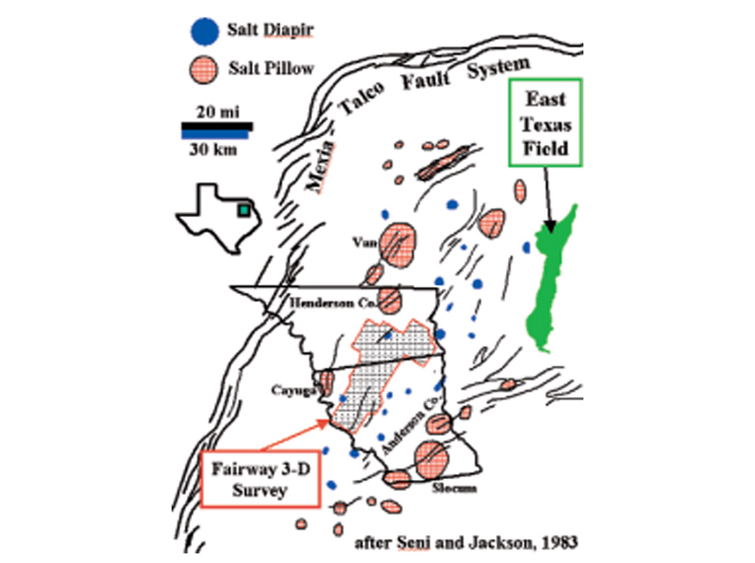
The northern part of the Fairway 3-D survey includes the La Rue salt dome, which is expressed as a detached, teardrop-shaped salt diapir (Figure 3). Top of salt at La Rue is at 4,450 ft (1,356 m) below the surface. The La Rue diapir has a rim syncline of thickened Lower Cretaceous rocks and lies below a deformed roof of Upper Cretaceous formations. A remnant of the Louann salt is identified in Figure 3, defined by strong top and base of salt reflectors. A single, strong reflector is present where salt is mostly absent (a salt weld), as seen in the right half of the section. A strong Cotton Valley Lime reflector occurs about 600 msec above the top of salt. This reflector was the main zone of interest by the oil industry in 1997, when the 3-D survey was first acquired. Although no Cotton Valley Lime production is known within the Fairway survey limits, the Coherence Cube data did identify a prospective anomaly northeast of La Rue dome. A Coherence Cube amplitude image of a faulted carbonate reef prospect is shown in an insert in Figure 3, captured from the coherence display of the Cotton Valley Lime horizon at 2.75 sec, or about 18,500 ft (5,640 m).
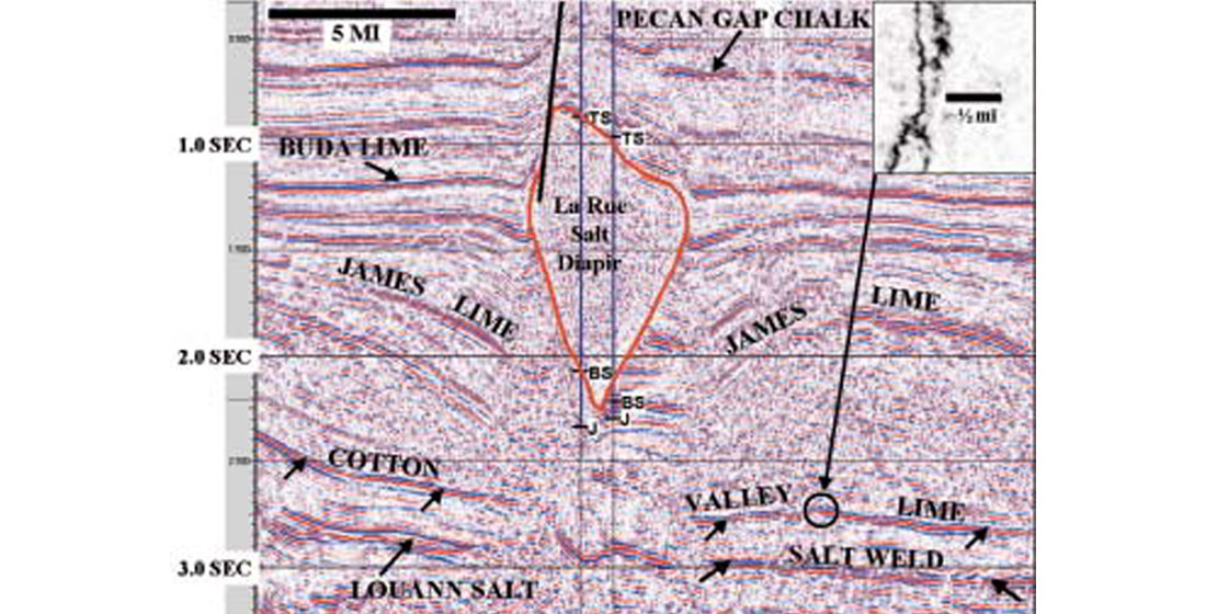
Figure 4 shows an east-west seismic section located a short distance south of the La Rue diapir. The seismic section has poor reflectivity between the Cotton Valley Lime and James Limestone.
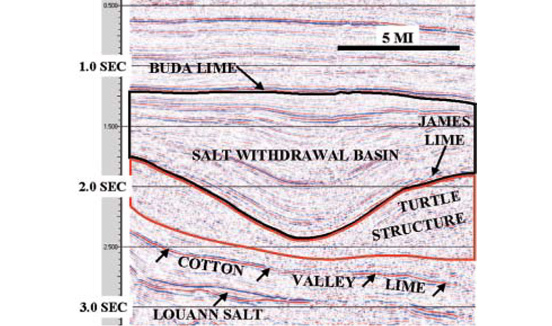
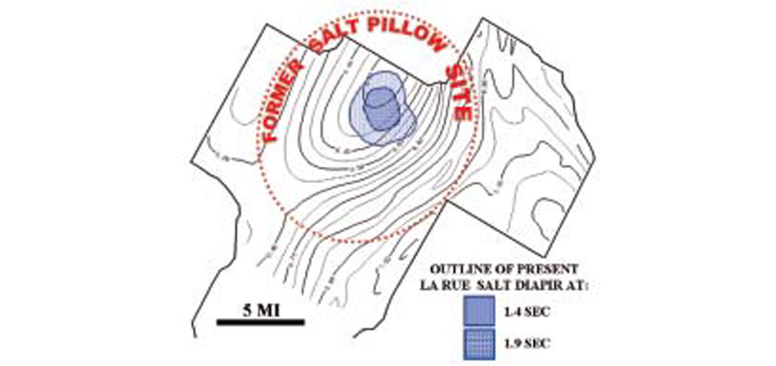
This interval is composed of deltaic/marine sandstone and shale of the Travis Peak, Hosston and Bossier formations. The two-way time (TWT) interval between the Cotton Valley Lime and James Limestone is displayed in Figure 5. The isochron contours exceeds 1.0 sec TWT in the eastern part of the survey and rapidly decreases to less than 400 msec TWT near the present site of the La Rue salt dome. Contours less than 600 msec form an oval-shaped closure oriented SSW-NNE. This contour pattern indicates that a salt pillow of considerable relief once occupied the area, and its former extent is estimated on Figure 5.
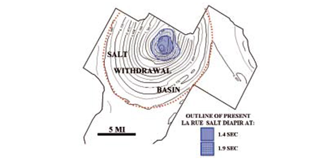
An isochron map of the seismic interval between the James and Buda limestones is shown in Figure 6. The contours exhibit a near circular pattern indicative of a local sub basin that is nearly coincidental with the site of the earlier salt pillow (Figure 5). One consequence of the growth of the salt pillow was the accumulation of extensional strain in the more brittle Late Jurassic — early Early Cretaceous rocks overlying the salt. Eventually these brittle rocks failed and extensional normal faults developed at the crest of the pillow. Opening of the extensional faults triggered the movement of salt to progressively enter the extensional fault zone from below and eventually reach the paleosurface as a salt diapir. The diapir was a very dynamic system that allowed large volumes of salt to leave the subsurface area, with salt eventually accumulating at or near the surface, dissolving by contact with ground or ocean waters. A consequence of the migration of salt from the pillow structure through the diapir was the slow, symmetric structural subsidence of the entire section above the deep salt pillow. This caused the paleosurface to sag and permitted thicker deposits of marine and deltaic sediments to accumulate, thus allowing a circular subbasin, or salt-withdrawal basin, to form.
Ring Faults
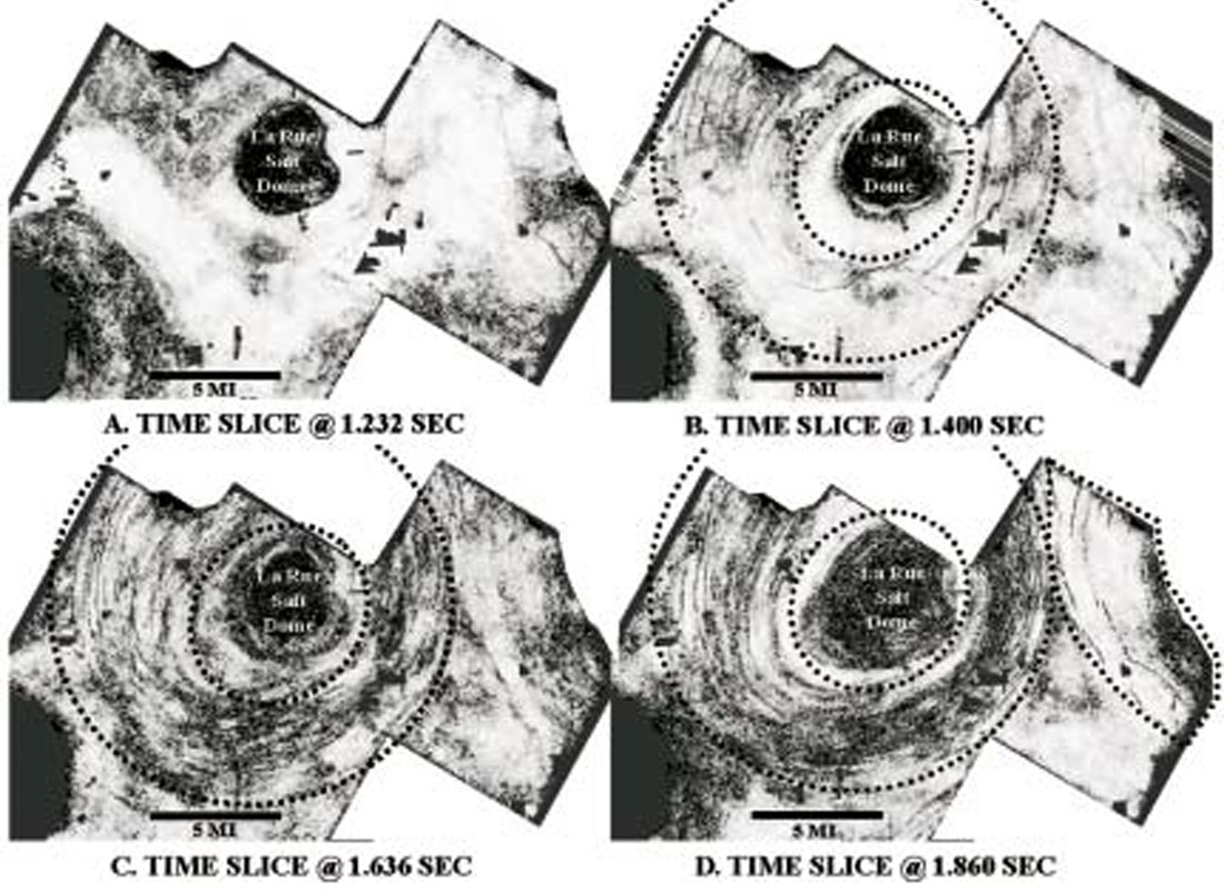
Coherence images revealed extraordinary sets of faults are present within the survey. Four sequential coherence time slices (Figure 7) at 1.232, 1.400, 1.636, and 1.860 sec cut through the salt withdrawal basin. Few faults are visible at 1.232 sec, but a set of en echelon, arcuate faults appear at 1.400 seconds and on the deeper images. These arcuate faults are more numerous in an annular belt between 4 and 9 miles measured outward from the present center of the La Rue salt dome, and appear more numerous due west and east of La Rue salt dome. Note the arcuate faults on 1.860 sec time slice near the eastern edge of the survey appear to define the presence of another salt withdrawal area, as these faults are concave to the east. The arc of these faults indicate they are association with the Brooks salt dome that is located several miles to the east. These arcuate faults are best described as “ring faults,” defined as a series of concentric normal faults formed by the collapse of rock in response to deep salt withdrawal. The faults do not form a continuous ring, but displacement from one fault overlaps with the next, forming a circular pattern, hence the term “ring fault.”
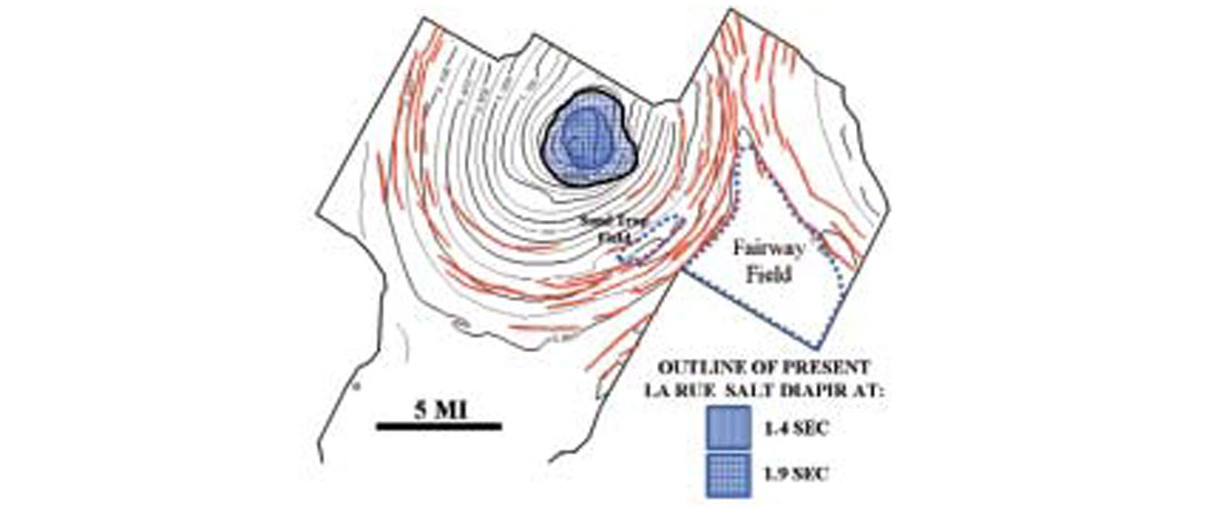
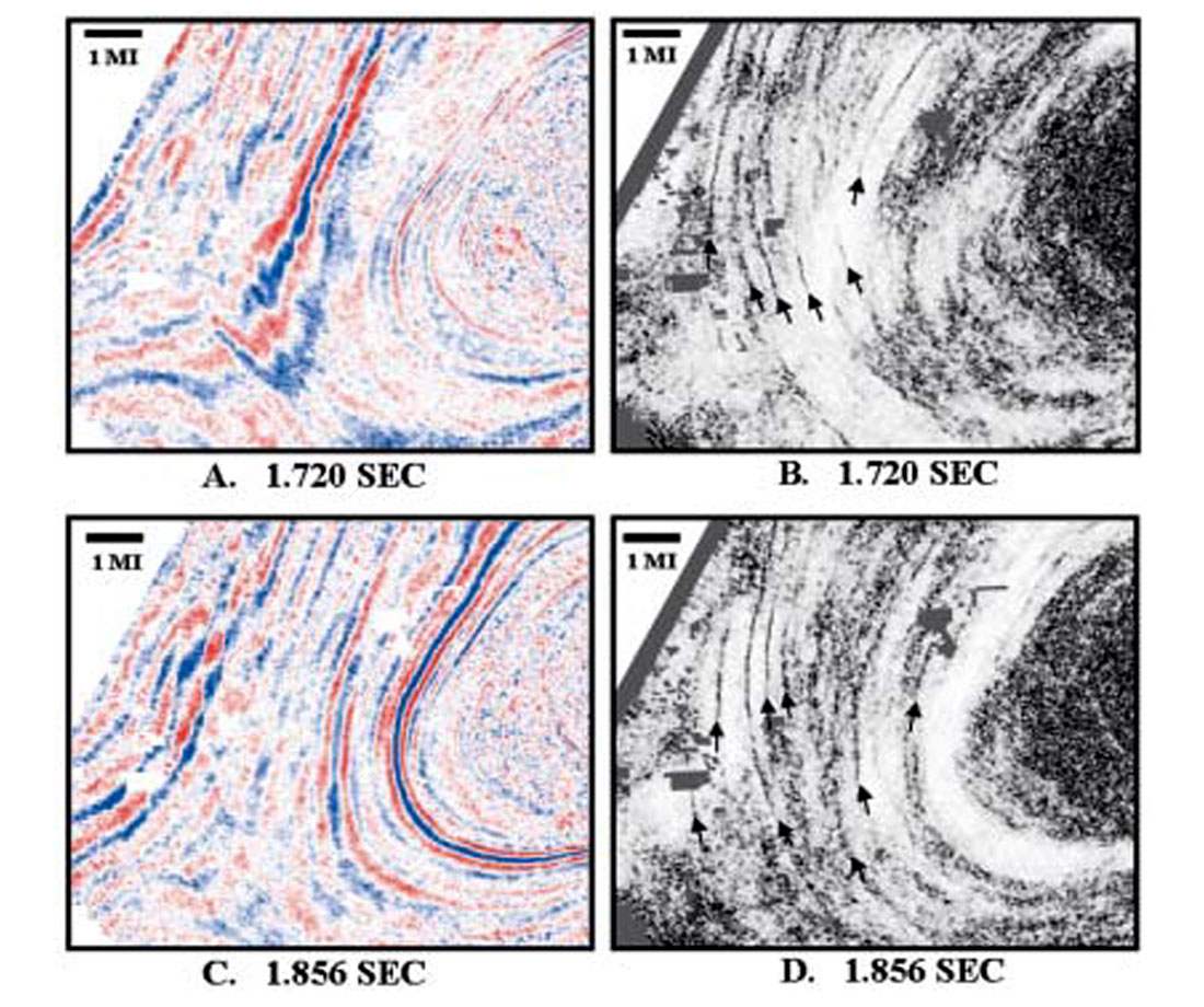
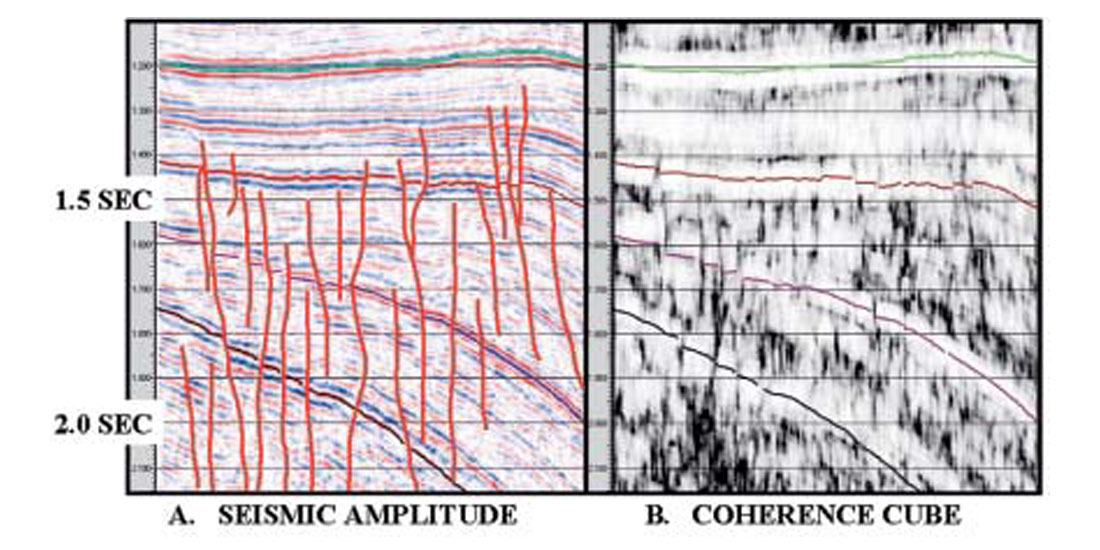
Ring faults mapped on a reflector near the top of the James Limestone are shown in Figure 8. The correlation between the ring faults and the isochron map of the James to Buda Limestone interval is readily apparent, suggesting a case for simultaneous origin for both features. The location of the Fairway and Sand Trap fields that produce from the James Limestone are shown. Figure 9 contains two pairs of seismic and coherence time slices (A & B, C & D) from an area west of La Rue dome. Without coherence processing the identification and mapping of the ring fault system would be challenging. Notice that faults seen on the coherence images strike at an acute angle to the apparent strike of bedding on the seismic amplitude time slice. Note that the ring faults (Figure 10) terminate near 1.3 sec. These ring faults can be classified as “blind faults” since as they do not offset shallow formations. Vertical throw on each fault measures between 10 and 25 msec TWT (65 to 170 ft; 20 to 52 m). Observations of these faults at greater depth indicate that they do not cut the Cotton Valley Lime, but appear to die out into the Bossier Shale and Travis Peak formation.
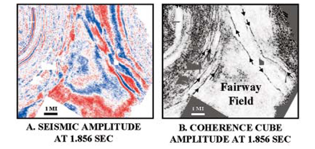
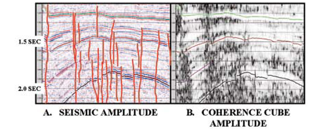
A pair of seismic amplitude and coherence time slices (Figure 11) was examined in the vicinity of the Fairway oil field southeast of La Rue dome. Fairway oil field, discovered in 1960, has produced over 209 MMBO and 790 BCF from the James Limestone reservoir. The western limit of the field is well constrained by ring faults associated with the La Rue salt withdrawal basin, while the eastern limit of the field is defined by ring faults associated with the Brooks Dome salt withdrawal basin. A matched pair of seismic amplitude and coherence section views near the northern limit of the Fairway field is shown in Figure 12. Faults mapped on the coherence section are shown on the seismic amplitude section. Notice, again, that most faults die out vertically near 1.3 sec.
Geological Evolution of Ring Fault System
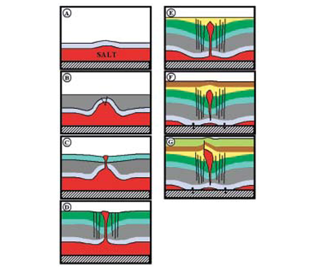
In a series of seven schematic diagrams, shown in Figure 13, the geologic history of the La Rue salt dome and ring fault development is summarized, incorporating the new geologic insights provided by coherence processing of the Fairway 3-D seismic survey:
During deposition of Cotton Valley Lime (Figure 13-A) the Louann salt beds responded to Late Jurassic sediment loading by forming small-amplitude salt swells. Concurrent with sediment loading by the north-to-south prograding deltaic sandstone and shales of the Bossier and Travis Peak sequences a large amplitude salt pillow developed (Figure 13-B). Growth of the pillow structure created strain in the brittle post-salt Jurassic formations and led to extensional faulting at the crest of the pillow. This faulting triggered vertical salt movement, allowing salt to flow into the base of the fault and form a diapiric mass that exploited the extensional fault zone to rise and reach the surface.
During deposition of James Limestone (Figure 13-C) the juvenile La Rue salt diapir entered its main period of growth during which the net accumulation of salt at the surface exceeded the rate of sedimentation, allowing the surface salt dome to grow. Movement of large volumes of salt from the pillow and into the diapir triggered the growth of the salt-withdrawal basin.
During deposition of Paluxy Formation (Figure 13-D) the Louann salt continued to migrate through the diapir, forming an ocean bottom salt glacier, or dome, that reached 12 mi≤ (31 km≤) in area. Continued migration of salt from the pillow structure and into the diapir allowed the overlying rocks to subside, forming a salt-withdrawal basin that expanded outward to include an area of about 170 mi≤ (440 km≤). It is estimated that 55 km3 of salt migrated from the pillow and mother salt areas via the diapir system. Salt that was not preserved in the expanding salt “deposit” at the sea floor was lost to dissolution from contact with ocean water. About 10 km3 of salt remains within the La Rue salt dome. It is estimated about 45 km3 of salt that transited the diapiric system was lost to dissolution at or near the seafloor in Early Cretaceous.
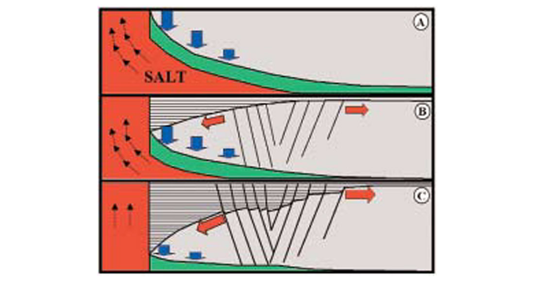
The sets of ring faults that populate the withdrawal basin section are the results of extensional tectonics. Figure 14 depicts the sequence of events that led to the formation of ring faults. As the salt evacuated from the deep layer, horizontal strain increased in the upper levels of the Travis Peak formation in response to uneven subsidence rates. Strain was relieved by the formation of ring fault system. The ring faults formed principally within a zone of maximum bending. This relationship explains why the ring faults are preferentially distributed in an annular zone 4 to 9 miles distant from the present center of the La Rue diapir. Note the formation of a graben in the central portion of the ring fault system, creating the geometry of footwall fault traps in portions of the ring fault system (Fig. 14C).
Near the end of the Early Cretaceous the nearly complete evacuation of deep salt, characterized by “grounding” of the hanging wall onto the former base of salt and formation of salt weld, brought the development of the salt-withdrawal basin and ring faults to an end. The 3-D data suggest that a palinspastic map depicting deposition of the Buda Limestone would exhibit very little surface relief associated with either the salt-withdrawal basin or diapir.
Thinning of the post-Buda sequences directly over the La Rue salt diapir indicates that the salt dome entered a post-diapir stage and became a positive paleotopographic feature during the early Late Cretaceous. Cut off from any additional salt influx from the deep salt beds, the La Rue diapir responded isostatically to continual burial, and possibly regional compression, by arching the overlying rocks in Late Cretaceous time (Figure 13-F).
In early Tertiary (Figure 13-G) more severe vertical salt movement ruptured the roof rocks of the diapir, forming a trap-door fault, with its principal displacement on the west flank. The trap door structure involves principally Upper Cretaceous formations younger than the Georgetown Limestone. Isostatically induced salt movement was unlikely to have formed the trap-door structure without the contribution of compressional stress. The required compressional stress likely originated from the Mexia-Talco fault zone updip to the west (Fig. 1). Mexia-Talco fault zone contains an en echelon array of grabens formed in response to basinward gravity gliding and spreading above the Louann salt. Transfer downdip of the resultant compressional stress likely boosted diapirism of the La Rue salt, uplifting and faulting the Upper Cretaceous overburden until the strain in the diapir was relieved.
Ring Faults and the East Texas Basin Petroleum System
Three major oil types have been identified in the East Texas Basin (Wescott and Hood, 1994) based on physical and geochemical characteristics of the basin: Jurassic, Lower Cretaceous, and Upper Cretaceous. The Jurassic oils are not restricted to a particular stratigraphic interval, but rather are found in reservoir rocks ranging in age from the Jurassic Smackover to the Upper Cretaceous Woodbine formations. Most of the oilfields in the East Texas Basin in which Jurassic-type oils have been identified are fault related, with faults either forming the trap or the trap being a highly faulted dome or anticline. Wescott and Wood (1994) observed a relationship between the amount of faulting and hydrocarbon production in the deep salt structures, and stated that those fields that are highly faulted have produced the largest amount of oil.
The ring faults that span the stratigraphic interval between the Upper Jurassic and Cretaceous formations could provide excellent vertical pathways for hydrocarbons to migrate from Upper Jurassic source rocks (Bossier shale) to Lower Cretaceous reservoir rocks. Development of ring faults during the Early Cretaceous could provide an early structural framework for the East Texas Basin petroleum system to flourish and provide hydrocarbon charge to the shallower reservoirs in faulted traps. Importantly, the blind fault character of the ring faults probably prevented any substantial loss of migrating hydrocarbons to the surface during peak periods of oil generation, estimated to have occurred between 88 and 20 m.y. An example of this fortuitous gathering of key petroleum system elements is demonstrated by the Lower Cretaceous James Limestone reservoir in the Fairway Field, which contains oil from Jurassic source rock. Ring faults border two of the three sides of the field and are well positioned to have played a role in charging the James Limestone reservoir with Jurassic oils. The high petrographic quality and thickness of the James Limestone reservoir in the Fairway field can be understood by its location atop the paleotopographic high that existed between the developing La Rue and Brooks salt withdrawal basins.
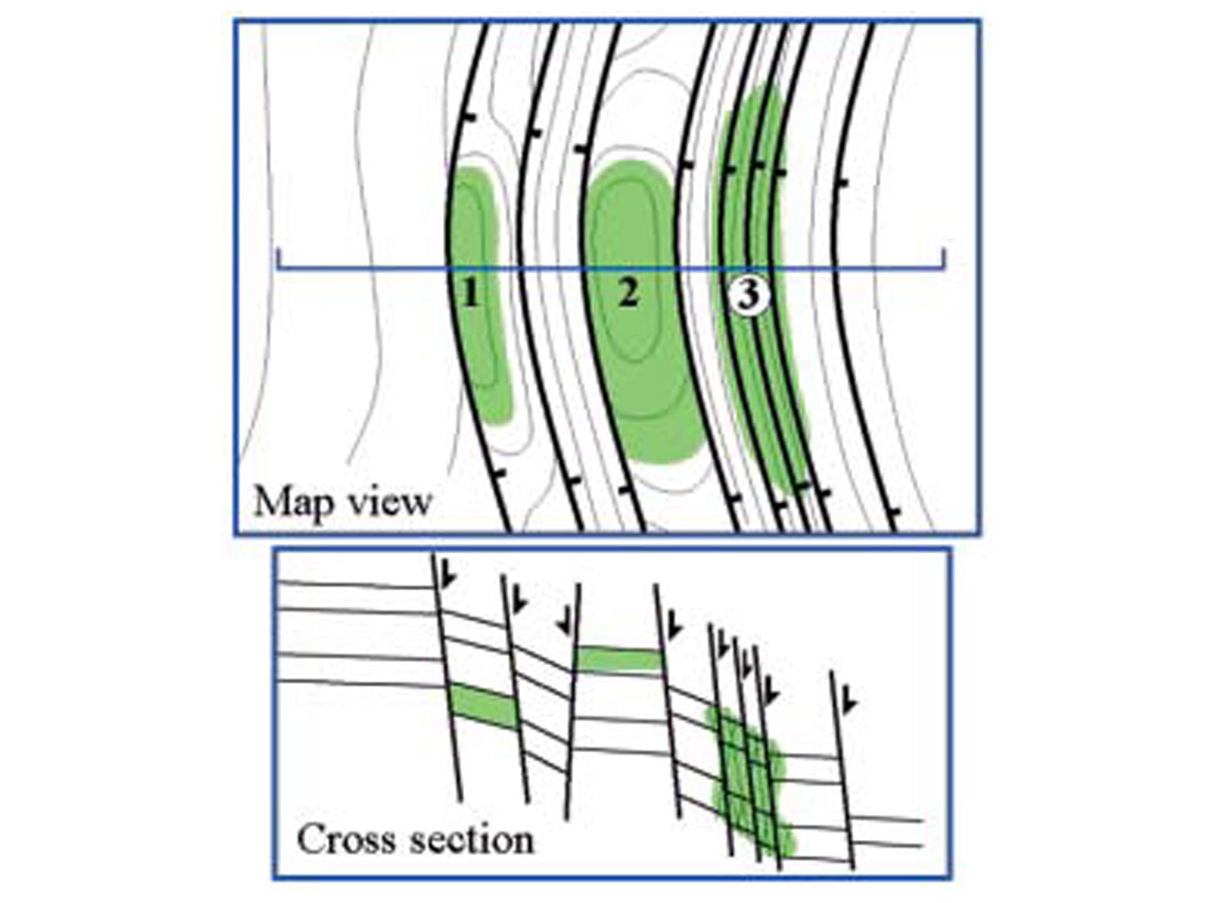
The discovery of ring faults associated with the La Rue salt withdrawal basin adds to the mix of structures that likely contribute to the creation of petroleum traps in the East Texas Basin. Recognition and mapping of ring faults with 3-D data can provide a basis for pursuing additional hydrocarbon exploration in this mature basin. A variety of structural traps can occur among the ring faults (Figure 15), the most common would be defined by two parallel ring faults accompanied by two- or three-way dips within the sedimentary rocks caught between the ring faults. Where complex relative ring fault displacements are present a horst block can occur between a pair of ring faults. This latter type of trap has been found productive in the Sand Trap gas field (cum. prod. 37 BCF) located immediately west of the Fairway field (Figure 8). A more speculative trap idea is the expectation that the closely-spaced ring faults may host fractured reservoir plays within Lower Cretaceous limestone and sandstone formations, even in areas of low porosity and permeability.
Ring faults are likely duplicated at other salt withdrawal basin sites within the East Texas Basin, but their complete mapping awaits coherence interpretation of other 3-D seismic surveys. Knowledge of the existence of ring faults associated with salt withdrawal basins in East Texas Basin is a key for effective exploration for traps located astride or adjacent to these principal migration pathways. Future petroleum discoveries are expected to follow detailed mapping of ring faults in the East Texas Basin.
Conclusions
Images derived from a 3-D Coherence Cube seismic volume in the East Texas Basin aptly exhibit extraordinary sets of closely-spaced ring faults that comprise the periphery of two salt withdrawal basins, one associated with the La Rue Dome and part of a second associated with Brooks Dome. The giant Fairway oil field is located at the junction of these two sets of ring faults.
The distribution and Early Cretaceous age of the ring faults establishes that these faults, unrecognized for their structural organization until this study, are a significant element in evaluating petroleum migration patterns and traps in the basin. The ring faults span the stratigraphic interval between the Upper Jurassic and Cretaceous formations and could have provided vertical pathways for hydrocarbons to migrate from Upper Jurassic source rocks (Bossier shale) and charge the shallower Lower Cretaceous reservoir rocks. Importantly, the blind fault character of the ring faults probably prevented any substantial loss of migrating hydrocarbons to the surface during peak periods of oil generation.
The structural style of high-angle ring faults creates a multitude of possible fault traps in a previously unattractive structural setting. Besides structural traps developed between ring faults, as found in the Sand Trap field, a more speculative trap idea is the expectation that the closely-spaced ring faults can host fractured reservoir plays within Lower Cretaceous limestone and sandstone formations, including rock volumes with low matrix porosity and permeability. Discovery of Early Cretaceous ring faults in the East Texas Basin by Coherence Cube processing brings new perspectives to development and exploration drilling in this mature petroleum province. Future petroleum discoveries may follow detailed mapping of ring faults in the East Texas Basin.

Acknowledgements
Acknowledgement is given to Schlumberger for permission to publish images from the Fairway 3-D survey and the assistance of Wayne C. Ackerman, formerly of Schlumberger, is gratefully acknowledged. Thanks to Dr. Bruno Vendeville, University of Texas at Austin, and Dr. Roger Sassen, Texas A&M University for stimulating discussions on salt tectonics and salt dissolution processes. Appreciation is expressed to the staff at Scott Pickford (successor to Coherence Technology Company), and parent organization Core Laboratories, for encouragement and permission to publish the results of this study.


Join the Conversation
Interested in starting, or contributing to a conversation about an article or issue of the RECORDER? Join our CSEG LinkedIn Group.
Share This Article