Historical Review
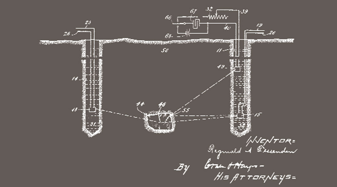
Fessenden’s patent of 1917 appears to be the first documented seismic application involving buried sources and geophones. One illustration from this patent is shown in Figure 1. In this diagram, item 49 is a borehole acoustic energy source, and items 15 and 18 are borehole acoustic receivers. Dashed lines 46 and 55 show possible travel paths of acoustic energy that interact with a buried ore body 44. In describing the method used to locate the ore body Fessenden states, “The vertical angle of reflection may be determined by hauling the transmitter 49 or the receivers 18, 15 up or down in the drill holes.” The rudiments of vertical seismic profiling (VSP) and crosswell profiling (CWP) can thus be traced back more than 80 years to the date of this patent.
In his analysis of how newly developing seismic methods could be used to map geological structures, Barton (1929) referred to Fessenden’s earlier work and described possible uses of seismic measurements in boreholes. McCollum and LaRue’s (1931) paper is significant in that they stressed that existing wells were not optimally used for collecting exploration data. Their proposal, that local geological structure could be determined by measuring traveltimes from surface energy source positions to subsurface geophones located in wells, is now an active and valuable application of modern vertical seismic profiling.
After McCollum and LaRue’s (1931) paper, enough of the essential elements and potential applications of vertical seismic profiling were captured in public geophysical literature so that VSP technology should have flourished and developed into a widely used procedure for hydrocarbon exploration. However, the worldwide geophysical community largely ignored the area of borehole seismology and placed its emphasis on surface recorded reflection measurements. The major use of boreholes for seismic purposes was, for several years, limited primarily to the measurement of seismic wave propagation velocities (Dix, 1939). These investigations led to the development of the valuable velocity check-shot survey technology that is now widely used across the petroleum industry.
Although the emphasis on borehole velocity measurements was invaluable for interpreting surface-recorded seismic data, that emphasis perhaps caused geophysicists to focus undue attention on just the information contained in the direct arrivals recorded by borehole geophones. It was not until the work of Jolly (1953), Riggs (1955), and Levin and Lynn (1958) that the potential of the total borehole geophone response was emphasized. These papers showed that rigorous wave propagation studies, interactions between primary and multiple reflections, and seismic wavelet attenuation could all be addressed by studying not just first breaks recorded downhole but the character of the seismic response that followed the direct arrivals. The present state of borehole seismic technology is to a large extent the result of the work done by these American geophysicists in the 1950’s. However, even though the value and applications of vertical seismic profiling were known and publicized by the mid-1950’s, geophysicists in the Western Hemisphere continued to use boreholes only for velocity measurements, not for rigorous vertical seismic profiling or crosswell profiling.
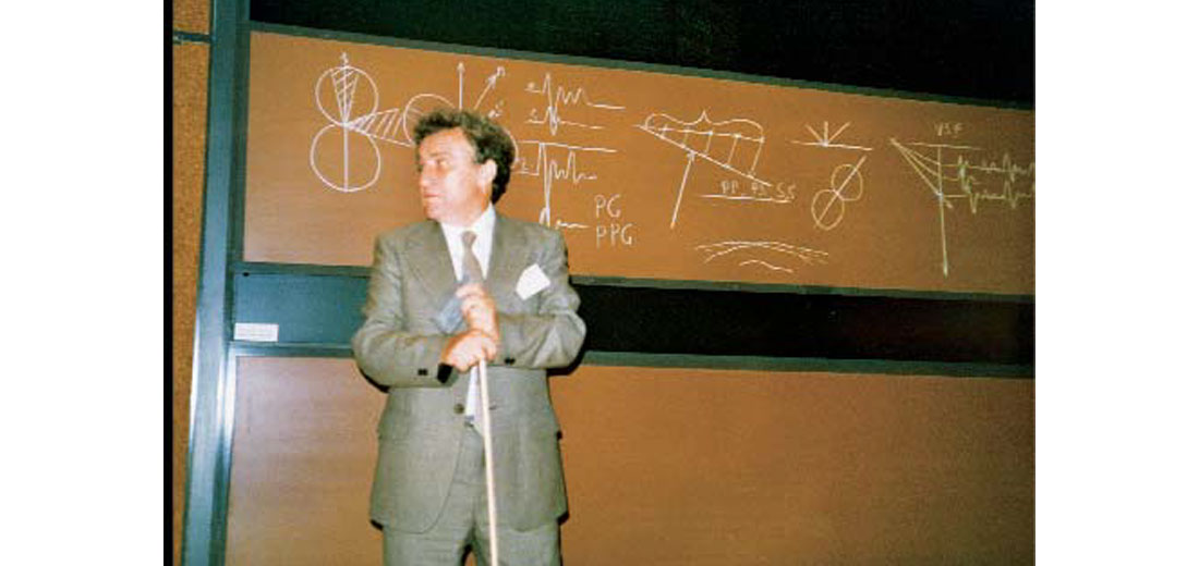
A different attitude existed among Soviet geophysicists. According to Gal’perin (1974, p. 2), VSP field work was initiated in the Soviet Union by the Institute of Physics of the Earth of the Academy of Sciences of the USSR in 1959. Documented studies of seismic measurements in boreholes then began to appear with considerable frequency in the Soviet Union in the 1950’s, and Soviet geophysicists aggressively developed VSP applications through the 1960’s and 1970’s. Gal’perin’s (1974) book provides an excellent description of this Soviet work and contains an extensive list of Soviet papers written during the 1960’s. In 1979, Gal’perin came to the United States as a guest of Phillips Petroleum Company, where this author was then employed, to help transfer VSP technology to American geophysicists. Figure 2 shows Gal’perin lecturing to a group at Phillips during this technology exchange visit.
The long lack of serious interest in vertical and crosswell seismic profiling in the Western Hemisphere cannot be easily explained or justified. Fortunately, in the late 1970’s and early 1980’s non-Soviet geophysicists began to publicize the need for increased emphasis on vertical seismic profiling. Early spokesmen in this VSP renewal were Kennett and Ireson (1973, 1977), Michon (1976), Omnes (1978), Anstey (1980), and Balch et al. (1980a, b). Books on VSP technology appeared (Balch and Lee, 1984; Hardage 1983, 1985), and numerous VSP short courses and workshops were taught publicly and privately in North America and Europe. Serious interest in VSP applications developed, and all aspects of VSP technology progressed steadily after this VSP revival in the late 1970’s and early 1980’s.
Very little crosswell seismic profiling was done in Soviet or non-Soviet countries until the mid-1980’s. Buoyed by numerous successful applications of VSP technology, geophysicists began in the mid-1980’s to explore methods of deploying seismic sources in deep wellbores rather than leaving the sources on the Earth surface, as is done in VSP data acquisition. Initial CWP data-processing emphasis was to focus on the traveltimes of crosswell first arrivals, which resulted in algorithms that created crosswell velocity tomograms.
This approach to CWP data analysis followed the path of VSP development where early (pre-1955) VSP emphasis was to create only vertical velocity tomograms (or checkshots) from first-arrival traveltimes. Whereas it took about 50 years (1930-1980) for VSP technology to shift to the concept of combining velocity analysis with near-borehole imaging, it required only about 5 years (~1985 to ~1990) for CWP technology to switch from velocity tomograms to applications that combined crosswell tomograms with interwell imaging. The text by Hardage (1992) summarizes the development of CWP technology up to the year 1990 and illustrates first-generation CWP procedures and applications.
VSP and CWP Technology Trends
Once VSP and CWP interest was rekindled in the 1980’s, important trends were set into motion to improve VSP and CWP data quality and expand VSP and CWP applications. Several key trends are described in this section.
Improvements in Receiver Design
One of the first technology shortcomings recognized was that the 1979-1980 style of downhole receiver had to be modified. Early receiver modules were huge by today’s standards, with typical parameters being a length of about 10 ft (3 m), a weight of about 150 lb (60 kg), and a weak locking force. These large receiver packages had resonances within the seismic bandwidth needed for most geologic imaging applications and did not couple horizontal geophones properly to the Earth.
Modeling studies and field tests showed that downhole receivers had to be as small and lightweight as possible to move resonant frequencies above the seismic signal band and that the horizontal locking force applied to receiver modules had to be 2 to 3 times the module weight to couple horizontal geophones properly to a formation.
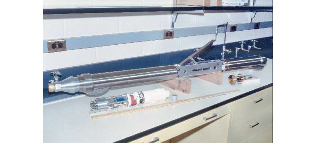
One of the early receiver modifications that focused on these needed changes was the receiver module developed at Phillips Petroleum in 1979-1980 (Fig. 3) shortly after Gal’perin’s visit to Phillips to assist in VSP research. This receiver was only one-third the size and weight of commercial receivers available at that time and generated a horizontal force 3 to 4 times the tool weight. Noticeable improvements in data quality, particularly on horizontal geophones, were achieved with this tool. The design of the downhole receiver module now used within Baker Hughes was directly influenced by this Phillips work.
The trend toward smaller and lighter downhole receivers dominated VSP and CWP receiver design through the 1980’s and 1990’s and continues today. The small receiver satellite used in Schlumberger’s CSAT tool is an example where receiver-miniaturization has taken the industry.
An equally important trend in downhole receiver design has been the effort to increase the number of receiver stations that can be deployed to record VSP and CWP data. First-generation tools could record data at only one depth level, which made data acquisition slow and arduous. Today, contractors offer multi-level receiver systems. VSP data are usually recorded with 3 to 12 receiver stations in a vertical array. Some contractors can deploy more than 20 receiver stations in a single array, particularly when recording CWP data.
Increase in Receiver Components
Early VSP receivers utilized only vertical geophones and provided only single-component data. Similarly, early CWP receivers tended to be free-hanging hydrophones that also provided only one-component data. The trend for the past several years has been to record both VSP and CWP data with clamped three-component geophones. In CWP applications where the receiver array needs to be moved many times, it is still attractive to use free-hanging hydrophones rather than wall-clamped receivers because considerable time can be saved by avoiding repetitive clamping and unclamping of a downhole array. The emphasis on multi-component data is driven by the need to use all elastic components of illuminating wavefields for subsurface imaging and seismic attribute extraction. Integration of compressional (P) and shear (S) images and combinations of P and S attributes provided by multi-component VSP and CWP data are sought by the industry to improve interpretations of facies distributions and stratigraphic relationships between key wells, provide more detailed descriptions of the internal architecture of complex reservoirs, and create more reliable models for reservoir simulators.
Conversion from Analog to Digital Data Transmission
First-generation downhole seismic data were acquired by analog transmission through standard seven-conductor logging cables from the downhole receiver to a surface-based recorder. This type of data acquisition restricted the number of data channels to three because only three independent wire pairs were available.
To increase the number of data channels and expand the number of receiver stations that could be used, industry devised technology that digitized data downhole, at the receiver stations, and then sent these data to surface-based recorders in digital form rather than as analog data. As a result, a trend has been to record a rather large number of data channels (16, 32, 48, ...) via standard seven-conductor wireline, which has allowed a wider variety of applications of borehole seismic measurements to be implemented.
Special Cables
The days of standard seven-conductor wireline logging cables may be numbered. New well logging tools amass huge data volumes (e.g., full-waveform sonic tools and various borehole imaging devices) and require fast, high-capacity data links to surface-based equipment that put excessive data-transmission demands on seven-conductor cable. The reluctance of logging companies to convert to fiber optic cable is that companies have such large capital investments in seven-conductor wireline that they are forced to continue to use these cables for economic reasons. Eventually, though, the industry will most likely convert to fiber optic cable technology for many downhole measurements that require large data files and fast data transmission.
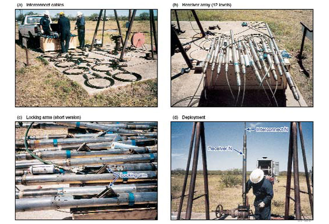
For the time being, VSP and CWP data acquired through major well logging companies will continue to be done with seven-conductor wireline. However, smaller service companies that specialize in VSP and CWP data acquisition rather than in general well logging have switched to special cables that provide efficient recording of large numbers of data channels. A fiber optic cable system offered by Geospace Engineering is shown in Figure 4 being deployed at the borehole geophysics test site operated by The University of Texas at Austin. Only 12 three-component receiver stations are being utilized in this instance, but the vertical array can be expanded to 32 stations or more if needed. Paulsson Geophysical Service offers a coil tubing system that contains enough analog wire pairs to accommodate 48 or more three-component receiver stations.
Recording Simultaneous Vibrator Wavefields
VSP users often want to record data from more source offsets than time and money budgets allow. The High Fidelity Vibrator System (HFVS) patented by Mobil (Allen et al., 1998) is a new field procedure that allows this objective to be achieved in onshore VSP programs that utilize vibrator sources. In the HFVS technique, wavefields from vibrators at several different Earth locations have unique phase shifts and are recorded simultaneously by a downhole receiver array. The composite wavefield is then processed to extract the wavefield response corresponding to each source station.
Vibrators must be equipped with Pelton Advance III electronics (or an equivalent) that record the ground force behavior for each phased vibrator during its total sweep. The ground force input from each vibrator is then used in a patented inversion scheme to segregate the composite response into each vibrator’s individual wavefield.
VSP contractors (e.g., Schlumberger) have licensed this HFVS technology and offer it as a source option in onshore VSP applications. Private contacts in the industry have confirmed that wavefields from as many as seven vibrators have been extracted from composite VSP responses, with each wavefield having signal- to-noise properties that are adequate for VSP imaging. This ability to record numerous source offsets in the same clock time required to record one source offset can be a significant factor in numerous VSP applications.
Miniature Geophones
Recent efforts have successfully miniaturized downhole geophones so that new deployment options can be considered. Los Alamos National Laboratory (Albright et al., 1997a, b) has tested one system that uses geophones having a diameter of only 0.5 inch (1.25 cm). These geophones can be packaged so that they can be deployed in the casing annulus of most wells or in small-diameter production tubing. These deployment options allow VSP data to be acquired in producing wells without pulling tubing and with reduced impact on well production.
CiDRA Corporation has made impressive advances in developing Fiber Bragg Grating (FBG) sensors that are the current ultimate in miniaturization. The fundamental sensor element is a fiber optic strand only 9 microns in diameter (25 microns with coating). This fiber can be wrapped on casing or tubing to create a permanent vertical array of sensors in key seismic monitoring or observation wells. Field tests of this sensor technology are being done at the Devine Test Site, a public borehole seismic test facility operated by The University of Texas at Austin.
VSP and CWP Software Trends
Trends in VSP and CWP data-processing and software development are less dramatic than trends observed in VSP and CWP hardware modifications. There does not seem to be any dominant focus or strong emphasis on new software algorithms or data-processing strategies. Standard, time-proven techniques for wavefield separation (FK, median, and tau-p filters) are still used widely. Singular-value decomposition (SVD) of wavefields into their component eigenfunctions has been proven to be a powerful wavefield separation procedure in both the time-space domain (Freire and Ulrych, 1988) and the spectral domain (Mari and Glangeaud, 1990).
The appeals of spectral SVD approaches to wavefield separation are that the technique works when the velocity structures of the component wavefields overlie each other and picking first-break times is not necessary. The principal assumptions are that the number of wavemodes is less than the number of traces in the wavefield and the amplitudes of the wavemodes that need to be segregated are significantly different at all frequencies. These assumptions are usually valid as far as direct and scattered VSP and CWP events are concerned, but the amplitude assumption may not be valid when comparing direct P-wave and S-wave events. Thus, spectral SVD may not in some instances be capable of separating direct P-waves from direct S-waves, nor reflected P-waves from reflected S-waves. However, if the technique segregates the high-amplitude, direct wavefield from the low-amplitude, reflected wavefield, then conventional velocity filters can usually separate these two wavefields into their P- and S-wave components.
Iterative techniques that adjust slowness fields until calculated traveltimes along curved raypaths agree satisfactorily with measured traveltimes have become robust methods for positioning VSP and CWP reflection points. Justice et al. (1988) and Justice and Vassiliou (1990) demonstrated this approach in CWP data processing. Rather than calculate curved raypaths, they instead solved a wave equation algorithm at each iteration step to define curved wavefronts across slowness fields.
There are some equivalences between conventional, film-based, optical holography and crosswell seismic recording. In the crosswell situation, both a direct and a scattered wavefield are recorded as in optical holography. However, these seismic wavefields are captured by point receivers, not on a film medium, so a different image reconstruction must be used. Basically, mathematical operators must be designed that produce a double focusing action by first backpropagating the receiver array response, and then backpropagating the source array response. The mathematical details of the construction of these wavefield-focusing operators can be reviewed in Wu and Toksoz (1987), Pratt and Worthington (1988, 1990), and Pratt (1990). These authors pointed out the similarity between holography and geophysical diffraction tomography, with the primary difference being that diffraction tomography is a valid imaging technique only when the interwell scatterers are weak (e.g., when the interwell impedances differ by no more than 10 to 15 percent). In contrast, holography is valid when strong impedance changes occur. In these investigations, the conclusions that are reached are that the image reconstruction should be implemented for more than just one frequency and that multi-frequency, multisource holography becomes equivalent to prestack migration. An excellent review of CWP data-processing technology can be found in the book edited by Nolet (1987).
A point that must be emphasized in this overview paper is that a major need in VSP software is to develop low-cost 3-D VSP imaging and migration algorithms and procedures so VSP analyses are not limited to 2-D profiles.
Future Emphases
Prediction is risky in any field of endeavor. Prediction about technology uses in the roller-coaster atmosphere of the oil/gas industry is certainly suspect. Nonetheless, the following VSP and CWP technology trends seem to define the direction of future growth in the borehole seismic area.
Expansion from 2-D to 3-D VSP Imaging
Current VSP data acquisition and processing provides users only 2-D images. The advantages of 3-D seismic imaging over 2- D imaging have been documented many times across the industry. Thus it is necessary that VSP technology move from the 2-D imaging world to the 3-D world. The hardware and software required to produce 3-D VSP images exist. The barrier to true 3- D VSP imaging is cost, not technical capability. If VSP contractors focus on cost reduction to make 3-D VSP imaging competitive with surface-recorded 3-D seismic data, 3-D VSP imaging should become a popular option for resolving production problems, characterizing complex reservoir architecture, and monitoring production processes.
Calibration of P and S Surface Data
The industry is converting rapidly from single-component 3-D surface-recorded seismic data to three-component and nine-component land data and four-component marine data. Both compressional (P) and shear (S) images are produced when multi-component seismic data are processed. A major problem for interpreters of multi-component surface-recorded data is to develop a reliable procedure by which depth coordinates of key targets can be identified in terms of their P-image times and S-image times so that P and S attributes can be calculated over correct data windows to indicate facies distributions within targeted intervals. Multi-component VSP data are the most reliable way to establish a rigorous correspondence between stratigraphic depth and P and S image times. The increasing use of multi-component surface 3-D data dictates that multi-component VSP applications that assist calibration of surface-recorded P and S seismic data will likely be a major market for VSP technology for the next several years.
Smart-Well Technology
The concept of smart wells equipped with a variety of permanent downhole sensors that gather data needed by reservoir evaluation teams is the focus of much attention in the industry. Reliable, long-life seismic sensors are particularly requested by smart-well proponents. Some business strategies, for instance the Fiber Bragg Grating (FBG) sensors developed by CiDRA Corporation, are responding to this market potential. The goal of FBG manufacturers is to install permanent arrays of FBG sensors in key wells across reservoirs and then use these sensors to record data from both passive and active seismic sources that illuminate the reservoir system. Such arrays can record time-lapse VSP and CWP data without having to deploy wireline-based or coil-tubing-based sensor systems in wells. Smart-well implementation should become a major arena for VSP and CWP technologies over the next several years.
Time-Lapse Reservoir Monitoring
A major application for CWP technology should be time-lapse reservoir monitoring. Time-lapse reservoir monitoring via surface-recorded seismic data is becoming an accepted technology. The information gleaned from these repeated 3-D surveys should be confirmed and calibrated by borehole seismic measurements. Good-quality time-lapse CWPs recorded between wells that span reservoir changes inferred from surface 3-D data and across vertical sections that traverse fluid-contact boundaries determined from well data will be a reliable confirmation and calibration of surface-recorded data interpretations.
Summary
Standard applications for VSP and CWP data have been the calibration of stratigraphic depth with the image time portrayed by surface-recorded seismic data and the production of small high-resolution 2-D images around key exploration and production wells. These standard uses will continue to sustain borehole seismic contractors in the near term and should provide a modest financial basis for developing new technology for emerging industry trends.
VSP and CWP users and providers need to focus on only two or three new application areas, not a long list of possibilities, so that industry resources are not so overstretched that no progress is made on any front. This overview recommends four areas for future emphasis and growth: affordable 3-D VSP imaging, multicomponent VSP acquisition and processing for calibrating surface-recorded P and S seismic data, smart-well instrumentation and applications, and time-lapse reservoir monitoring.
One obvious omission from this list of future emphases is single-well profiling, (SWP), where both source and receivers are deployed in the same well. There are intriguing applications, such as salt flank imaging, that can be implemented once SWP technology is available. However, the author’s opinion is that the cost and time budgets required to develop a robust SWP technology are excessive in this current environment of shrinking capital budgets and reduced technical staffs. The industry will probably be better served for the next few years by concentrating on only the four areas suggested in this review paper.


Join the Conversation
Interested in starting, or contributing to a conversation about an article or issue of the RECORDER? Join our CSEG LinkedIn Group.
Share This Article