Introduction
In 3D seismic acquisition it may happen that in some areas sources are not allowed whereas geophone planting is permitted. Examples of such areas are nature reserves, parks, lakes, and other sensitive areas. Often, it might be possible to circumvent the problem by using weaker sources or using buried sources (e.g. Wood et al., 1999) but this is not always feasible.
There are two main consequences of missing shots in the obstacle area: 1) missing short-offset traces inside that area and 2) reduced coverage outside the area. The first problem can be mitigated somewhat by adding sources along the perimeter of the obstacle, but combinations of a shot and a receiver both situated inside the obstacle area cannot be compensated for. The second problem is more amenable to a solution, but I have not seen solutions that really solve it. Millis and Crook (2012) tackle the same situation and also propose infill receivers as a solution, yet their solution does not address the problem from an offset-vector point of view, which is really essential, I believe. In this paper I propose a solution based on optimising offset-vector tile (OVT)-gathers. Those singlefold gathers can play an important role in anisotropy analysis and in prestack migration (Vermeer, 2012).
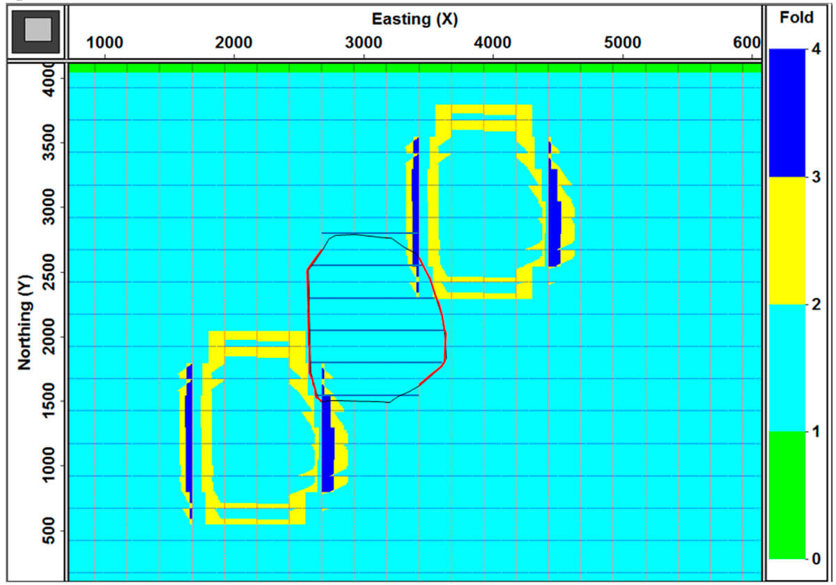
A solution that has been popular in the past is to deploy compensating shots around the obstacle. Using reciprocal OVT-gathers Figure 1 illustrates such a solution with a relatively large number of compensation shots. The acquisition geometry used in this example (and in all other examples in this paper) consists of a regular orthogonal geometry with station intervals of 12.5 m, line intervals of 250 m, and maximum inline and crossline offsets of 3000 m. In the fullfold area of this survey total fold equals 3000/250 x 3000/250 = 144. The OVT-gathers in Figure 1 have inline offsets 1500 – 2000 m and crossline offsets 1500 – 2000 m. Because reciprocal OVTs are used the corresponding negative offsets are included as well. The fold for any reciprocal pair of OVT-gathers is equal to 2 inside the fullfold area of the geometry (see subfigure in Figure 1a). The perimeter of the area where no shots can be taken is indicated with a black curve in Figures 1a and 1b. Figure 1a shows coverage for the situation without any compensating shots. It shows two green areas (one for each reciprocal OVT-gather) where coverage is reduced to 1 because of the missing shots in the obstacle area. Figure 1b illustrates the effect of adding extra shot-line segments: the green areas are only somewhat reduced, because the compensation shots mainly increase fold in areas where fold does not need to be compensated; fold becomes larger than 2 in those areas.
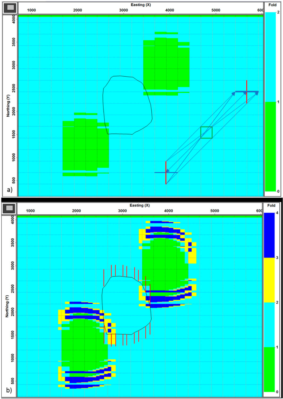
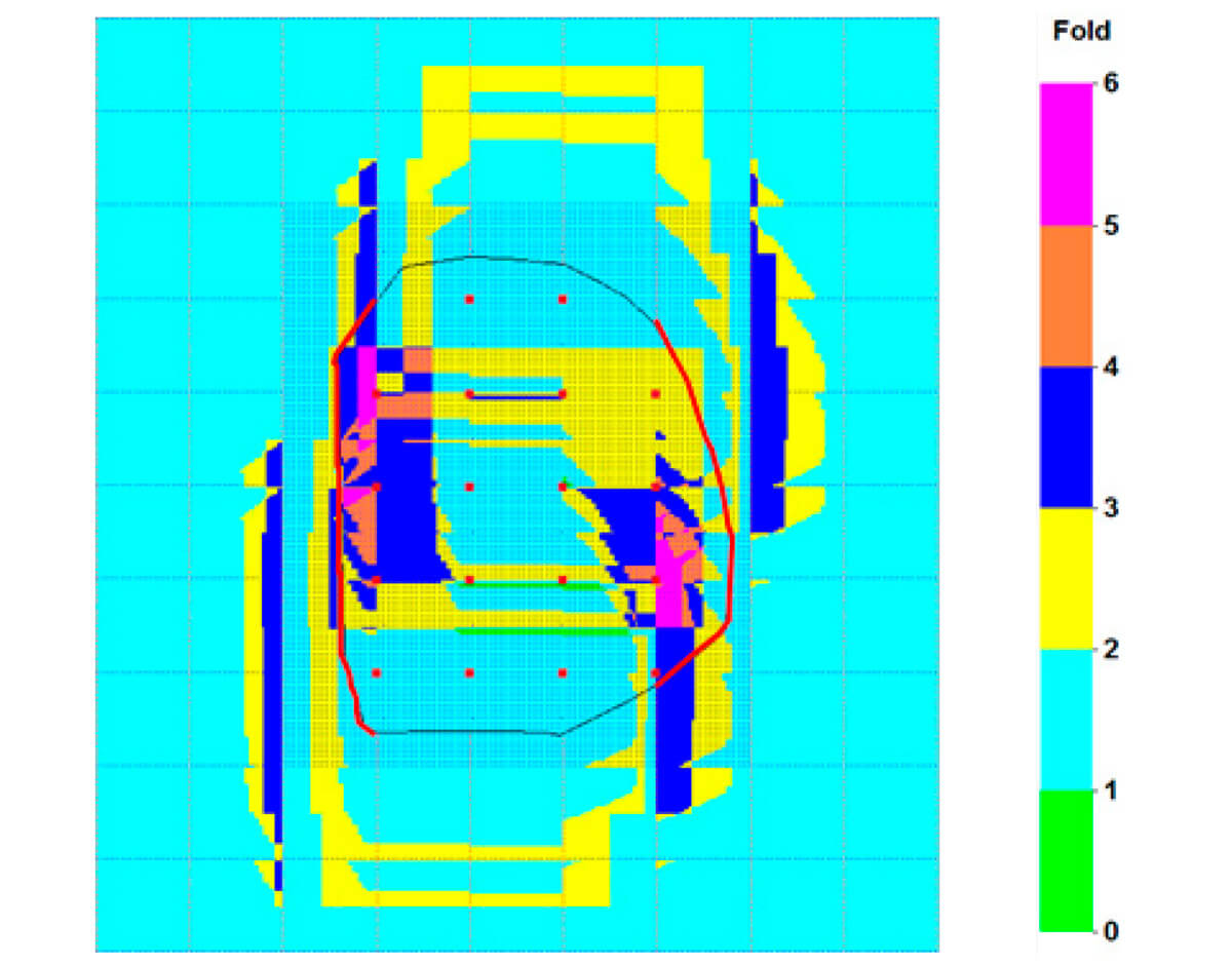
It is interesting to note that the two green singlefold areas in Figure 1b have similar size as the obstacle area. The size of the areas is about 16 unit cells. This means that the singlefold area of neighbouring OVT-gathers would overlap partially with the singlefold areas of Figure 1b. Figure 2 illustrates this effect for 16 OVT gathers with their reciprocal counterparts and offset ranges 0 – 2000 m in inline as well as in crossline direction. The two green areas correspond to reduced coverage and the small pink areas represent a fold of only 16, whereas regular fold would be 32. So there is a serious shortage of coverage in those green areas. On the other hand, the reddish areas indicate locations where there are more traces in the specified offset range than required.
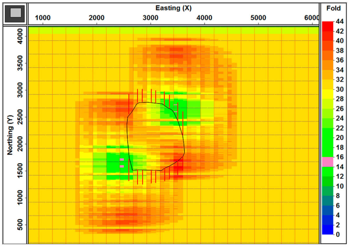
Figure 1b and Figure 2 illustrate that this method of compensating shots does not work well for the missing traces outside the area of the obstacle. In the following I show that using compensating receivers laid out inside the obstacle area can regularize coverage outside it. First I illustrate the mechanics of using additional receivers, followed with illustrations using the same obstacle as in Figure 1.
The benefit of extra receivers
The idea is to lay out extra receivers halfway between the existing receiver lines . Of course, the required extent of the extra receivers is dependent on the size of the obstacle; this section discusses the optimal extent.
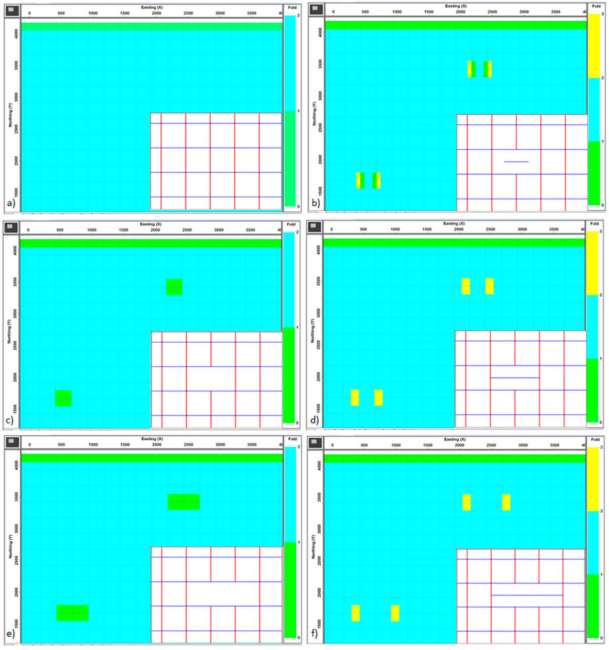
A shot/receiver pair that cannot be acquired because the shot is not allowed has to be compensated by a shot/receiver pair that has nearly the opposite azimuth and nearly the same absolute offset. So, the compensating shot/receiver pair should be nearly reciprocal to the missing one. And this should apply to all missing shot/receiver pairs. This looks like a tall order, but it can be done as illustrated for some simple cases in Figure 3.
Again, two reciprocal singlefold OVT-gathers are used in Figure 3 to illustrate the effects. The inserts show enlarged configurations. The left column illustrates a) no missing shots, c) one missing shot-line segment, and e) two missing shot-line segments. In Figure 3c there are two small singlefold areas, each the size of a unit cell and in Figure 3e there are also two singlefold areas, now with double the size as in Figure 3c.
The most instructive result is shown in Figure 3b with as many replacement receivers as there are missing shots. The green areas as shown in Figure 3c are only partially covered with compensating traces; half of the areas are still singlefold. There are 3-fold areas just outside the originally green areas.
The reason for this behaviour is that a shot line shooting into the line segment of extra receivers can only generate inline coverage with half the length of the segment. The width of a unit cell can only be reached if the line segment of receivers is twice as long like in Figure 3d. The next shot line generates also half a unit cell width of which one half satisfies the requirements of the OVT-gather under investigation. Therefore, the small yellow areas have a width of one quarter of a unit cell.
The solution illustrated in Figure 3d does cover the complete missing unit cell. One shot line takes care of filling in and the two shot lines on either side of the central one produce redundant coverage, each one with a width equal to half a unit cell. Figure 3f shows that for two missing shot-line segments the length of the line of replacement receivers must be equal to three unit-cell widths.
The general conclusion from this exercise is that for complete replacement of all missing shot/receiver pairs the replacement receiver lines should extend up to the uninterrupted shot lines. Another point to make is that inserting extra receiver lines across the whole survey area is tantamount to doubling the crossline fold of the geometry. Inserting extra receiver lines only where shots are missing ensures that the missing coverage is properly replaced.
Experiments with an irregularly shaped obstacle
For these experiments I use the same obstacle as used in Figure 1. The first experiments using only compensating receivers are followed by an experiment with extra shots as well.
Adding compensation receivers
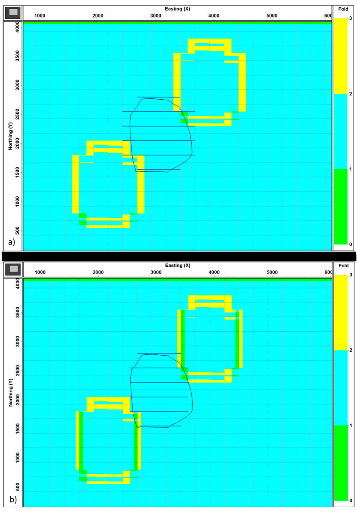
After the lessons from Figure 3 the first experiment involves using extra receiver lines that extend from a continuous shot line on one side of the obstacle to a continuous shot line on the other side. The result is shown in Figure 4a for reciprocal OVT-gathers as in Figure 1. Comparing Figure 4a with Figure 1b shows a large improvement in coverage: the green areas in Figure 1b are filled almost completely in Figure 4a. There are still a few small singlefold areas in Figure 4a. These areas are there because the most southerly compensation line does not extend to a complete shot-line segment. On the right it extends to a shot-line segment that is nearly complete, so it leaves a very thin strip of singlefold bins. On the left it extends to a shot-line segment that is even smaller than half a shot-line interval, thus producing a thicker strip of singlefold coverage.
For completeness sake Figure 4b shows infill receiver lines that only extend halfway between two shot lines (except the most northerly line and the most southerly line). Now singlefold coverage extends all along both sides of the infill area. Clearly Figure 4a gives more complete coverage than Figure 4b. Yet, it may also be argued that the missing coverage in each strip is kind of compensated by extra coverage in a neighbouring strip.
Adding compensation shots and fewer compensating receivers
This solution is prompted by the desire to minimize the area with missing short offsets. The closer one can place shots to the obstacle area the better the coverage of the short-offsets. Figure 5 shows the result of moving two of the interrupted shot lines to the perimeter of the obstacle for the same reciprocal OVT-gathers as before. Note that the applicable receiver-line segments now only extend up to the two curved shot lines along the perimeter of the obstacle.
Like before, all missing coverage is compensated in Figure 5. Apart from the inevitable areas with 3-fold coverage there are also 4-fold vertical strips on either side of the infill coverages. This effect is caused by the closeness of the curved shot lines to the adjacent straight shot line. Bending those straight shot lines somewhat would spread out the extra coverage, but it would not reduce the number of ‘redundant’ traces.
Minimizing the area with reduced short-offset coverage
The results in Figures 4a and 5 – full compensation of missing traces outside the obstacle area – are achieved for all reciprocal OVTs for which the offset vectors are sufficiently large. Unfortunately, the problem of missing short offsets inside the obstacle area cannot be solved completely satisfactorily, instead the best solution must be found.
Figure 6 shows short-offset coverage for the various infill strategies discussed before. The focus is on the OVT-gather with singlefold coverage that can be constructed from mini-cross-spreads as shown in Figure 6a. In a regular geometry the midpoint areas of all mini-cross-spreads together provide continuous singlefold coverage across the survey area. Each mini-cross-spread consists of a shot line and a receiver line of length 500 m that intersect in the middle.
Figure 6b shows coverage of the short offsets if there is no infill. Figure 6c shows this coverage for compensation shots as also used in Figure 1b. The area without coverage is reduced by 11%. Figure 6d shows an interesting result: no reduction of missing coverage to the right and to the left, but some reduction along the top and also the bottom for a total infill of 10%. Along the bottom it could have been better if the most southerly infill receiver line had extended out to a complete shot-line segment. Next, Figure 6e shows that the shot lines along the perimeter of the obstacle provide a considerably better result with 24% infill of short offsets, whereas the combination of shot lines along the perimeter and extra receiver lines in Figure 6f produces the best result of 33% infill. (The percentages infill are derived from the number of empty bins for the five situations: 29280, 25990, 26340, 22186, and 19620 for Figure 6b, 6c,6d, 6e and 6f.)
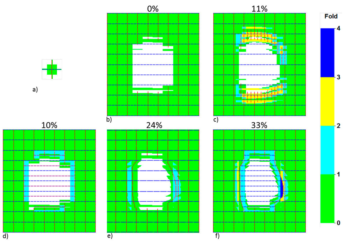
It is interesting to note in Figures 6d and 6f the difference in coverage around the most northerly and the most southerly extra receiver lines. In the North the empty bins (see Figure 6b) around the extra line are filled, whereas there are still a few empty bins around the southerly line. This difference is caused by the two interrupted shot lines around the middle of the obstacle. In the North these shot lines intersect with the extra receiver line, whereas in the South they do not.
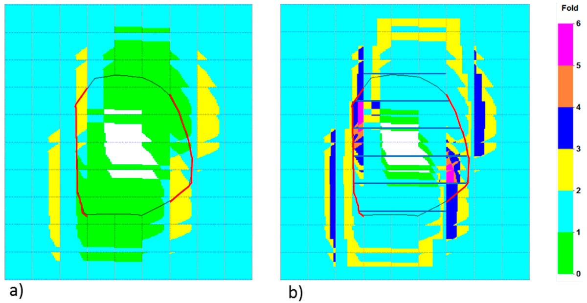
It should be realized that other somewhat larger offsets are also impossible to compensate for completely, depending on the size of the obstacle. Figure 7 illustrates this problem for the same geometries as in Figures 6e and 6f: curved shot lines along the perimeter of the obstacle area in Figure 7a and the combination of the curved shot lines with extra receiver lines in Figure 7b. Reciprocal OVT-gathers are used that represent offset vectors with a larger northerly component in the main direction of the obstacle. In both figures there are zones without coverage; these zones are somewhat larger in Figure 7a than in Figure 7b. Moreover, the addition of the extra receiver lines in Figure 7b does not only produce compensation traces outside the obstacle area but also inside it.
Inspection of fullfold maps
Figure 8 compares the four main geometries examined earlier. Figure 8a shows that fullfold coverage of the survey is definitely not satisfactory without any infill. However, in the map of Figure 8b fold in the central area across the obstacle is mostly larger than the nominal fold of 144, as it varies from 143 to 148 (not visible in the figure). Hence, total fold seems to be satisfactory, whereas we know from the earlier analyses in Figure 1b and 2 that coverage is not good for OVTs that need to be complete for optimum prestack migration. Because all OVTs have areas of higher and lower fold, total fold averages out to a large extent and hides the underlying deficiencies. This example illustrates the well-known fact that inspection of maps of fullfold coverage to determine the quality of a geometry can be quite misleading.
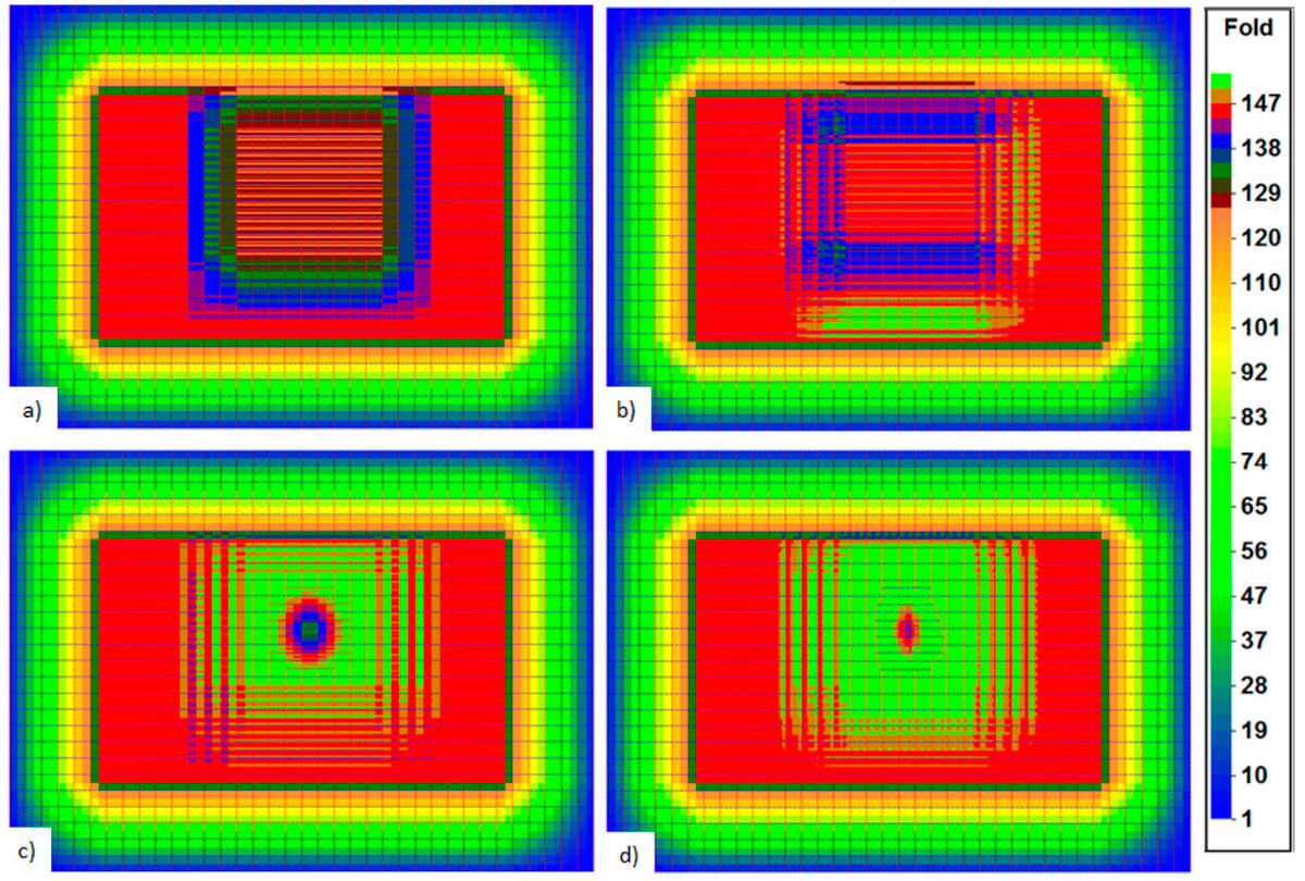
Fullfold for the geometry with compensating receiver lines is shown in Figure 8c. Again, there are areas with fold higher than nominal (151-152), now caused by the extra fold that is produced as a by-product of ensuring complete infill (Figure 4a). Right in the middle of the obstacle the lowest fold equals 133.
Figure 8d shows fullfold coverage for the geometry with shot lines along the perimeter of the obstacle together with compensating receiver-line segments. Maximum fold in the green area around the obstacle is now 158, whereas minimum fold in the centre of the obstacle is 140. The higher folds in this map compared to Figure 8c are caused by the curved shot lines being close to their neighbouring shot lines, leading to some 4-fold coverage in reciprocal OVTs (Figure 5).
What if at least some shots are allowed?
The larger the size of the area where shots are not allowed, the more short-offset traces will not be recorded. If just a few shots would be allowed inside this area, a totally different situation would result. There may be areas where environmental rules exclude a high density of shots, but where just a few might be permitted. Just for this kind of situation or similar an alternative approach might be to aim for a supplementary infill geometry that looks like an areal geometry.
For the example orthogonal geometry that has been used so far, the first thing to think of is the equivalent areal geometry with shot intervals equal to the two line intervals (300 x 300 m) and receiver intervals equal to the shot and receiver sampling intervals (12.5 x 12.5 m). This extra infill geometry is only intended to compensate for the traces for which both shot and receiver are inside the obstacle area.
The areal geometry used in Figure 9 consists of 18 shots and 30 unit cells filled with receivers. The underlying infill geometry is the one with shot lines along the perimeter of the obstacle. Comparing Figure 6f with Figure 9 shows that this approach of using a small areal geometry works quite satisfactorily. There are only a few empty bins left.
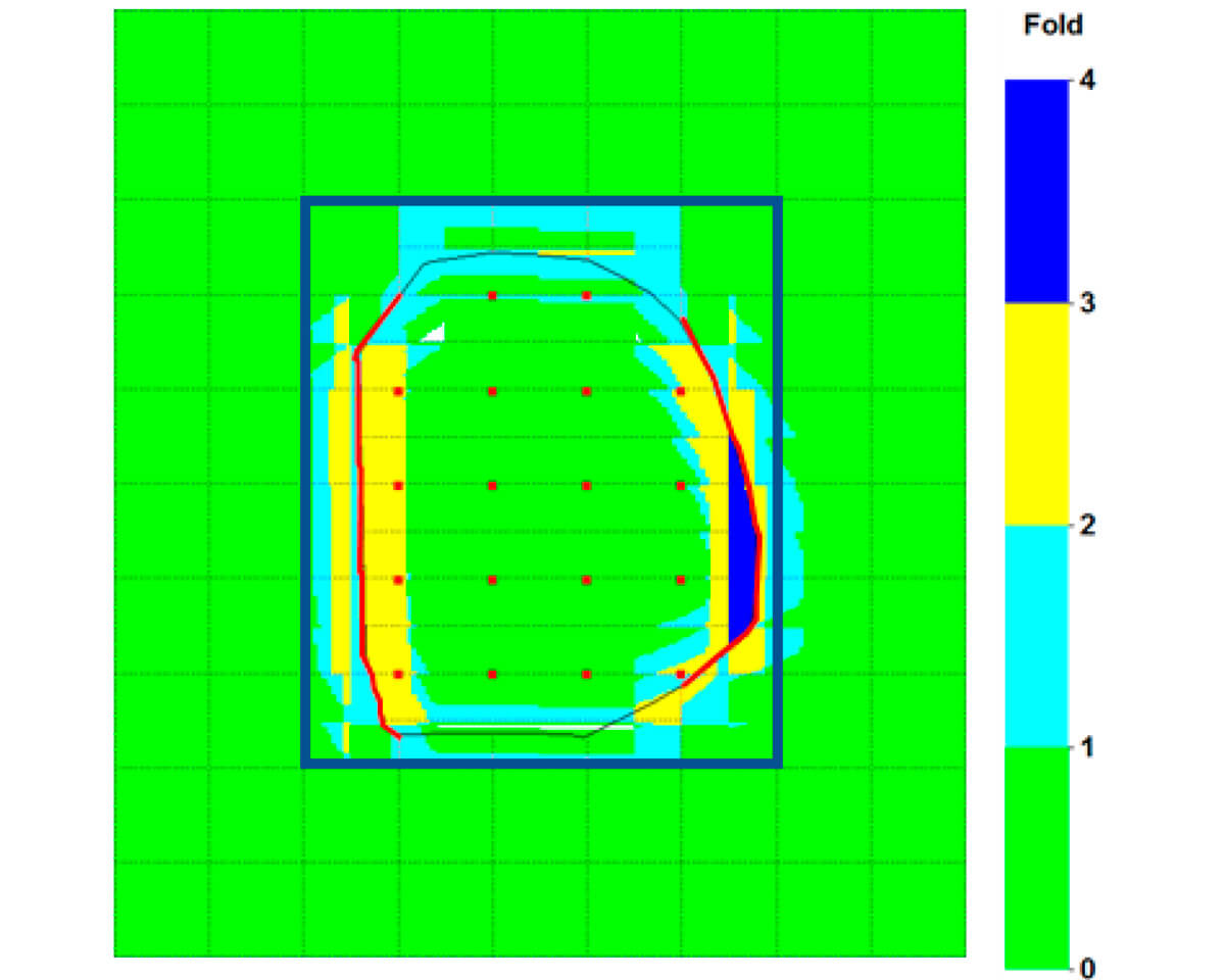
Figure 10 illustrates that also somewhat larger offset vectors may benefit from the infill areal geometry. Now the coverage of reciprocal OVT-gathers with offsets {(0, 500), (500, 1000)} is shown. This result may be compared with Figure 7b.
Laying out a 12.5 x 12.5-m grid of receivers seems like a serious challenge. It is, of course, but it can be done as shown recently when a sizable test survey was acquired with nimble nodes in a 12.5 x 12.5-m grid (Nehaid et al., 2019; Vermeer, 2020). The good thing is that this extra infill survey is almost entirely independent of the main acquisition (apart from the receivers that are used in the original infill geometry as well as in the areal infill); if so desired, it may be acquired at a later date.
The described regular grid of infill shots is the ideal arrangement. It would be most surprising if in a real situation such a regular grid would be possible. Yet, a few shots inside the obstacle area would always be better than no shots at all.
Discussion and conclusions
Compensating all missing shots inside an obstacle area with as many shots somewhere outside the obstacle area does maintain average fold but is not the best way of dealing with obstacles. Yet, this paper also shows that some compensating shots outside the obstacle area may be very useful.
The best solution to mitigate the effect of missing shots in an obstacle area consists normally of moving shot lines and adding receiver-line segments in two steps:
- Divert the two shot lines on the outside of a group of interrupted shot lines to the perimeter of the obstacle area. This action minimizes the area with missing short-offset traces.
- Add short receiver lines halfway the existing receiver lines. The first and the last extra receiver line should preferably intersect the shot lines that are interrupted further on because of the obstacle. All extra receiver lines should extend to complete shot-line segments (with length equal to a receiver-line interval). These rules ensure that all shot/receiver pairs with shot inside and receiver outside the obstacle area are compensated by shot/receiver pairs with receiver inside and shot outside the obstacle area with about the same absolute offset and with opposite azimuth
Laying out some additional short receiver lines to compensate for shots that cannot be taken is a solution that was not really obvious in the days of cable-based acquisition. With the advent of the self-contained nodes there is no problem anymore to insert those extra receivers.
In this paper an example obstacle area is used which has led to some general conclusions that can be extended to many real-life situations. Yet, it will always be essential to analyse coverage for the actual situation, because obstacle areas may have different shapes and orientations and also because in some areas straight acquisition lines are more the exception than the rule.
If there are several obstacles in the survey area then shot/receiver pairs with the shot located inside one obstacle area and the receiver located in another cannot be compensated with the method of additional receiver lines. This leads to missing coverage for the corresponding OVTs.
Any shots that can be taken inside the obstacle area will benefit the short-offset coverage across the obstacle. Such shots should be surrounded by an areal grid of receivers.

Acknowledgements
All analyses were carried out and figures were made with Omni 3D of Schlumberger. The idea of covering an obstacle area with receivers was prompted by reading the chapter on design in Jan de Bruin’s to be published book ‘What’s down below there?’ on 3D seismic data acquisition. I thank Kees Hornman and Jan de Bruin for their helpful suggestions for improvement of this paper.


Join the Conversation
Interested in starting, or contributing to a conversation about an article or issue of the RECORDER? Join our CSEG LinkedIn Group.
Share This Article