Summary
Shale reservoirs are characterized by extremely small pores and very low permeability. Detection and quantification of these small pores is a challenge. Furthermore, in such small pores, the gas flow need not flow in a Darcy flow regime. The Knudsen diffusion and slip flow gain significance and might account for at least partial flow. This flow depends on the pore size as well as the internal fluid pressure. Thus, in a depleting reservoir, the flow regime might change given a fast drawdown and loss of fluid pressure. It is postulated that gas flow in shale gas reservoirs falls in the transition regime between Darcy and Knudsen flows. The intermediate flow regime is modeled as a combination of Knudsen flow and Darcy flow. In this paper, we show how to compute the contribution of Knudsen flow to total flow as a function of pore-size and fluid pressure.
Introduction
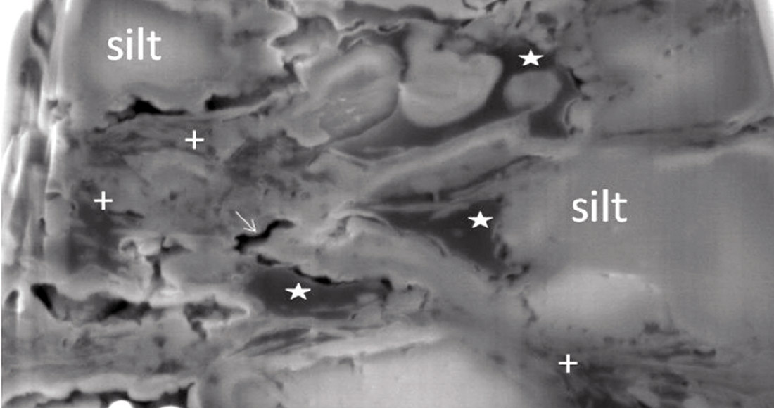
Over the last decade, gas shale plays have become the major source of natural gas production in the United States. In spite of their large proven and potential reserves, they possess many unique challenges. The concept of porosity, permeability and flow that is applied in conventional plays cannot be directly applied to shale reservoirs. These reservoirs are extremely fine-grained rocks with more than 50% clay as a part of their matrix. Shale matrix has predominantly micro (pore-width less than 2 nm) to meso pore [pore-width 2-50 nm]†. The presence of clays and organic materials result in extremely fine pore sizes and low permeability in nano-Darcy range. Gas production from these resources is much greater than anticipated and cannot be described by conventional wisdom. In this paper, we will review several different approaches to gas flow in shales. We will specifically show the applicability of Knudsen flow regime in modeling gas-flow in shale for laboratory measurement and reservoir engineering applications. An SEM image of a typical shale reservoir rock is shown in Figure 1. In the image (Figure 1), cracks and larger pores are visible but not the smaller pores.
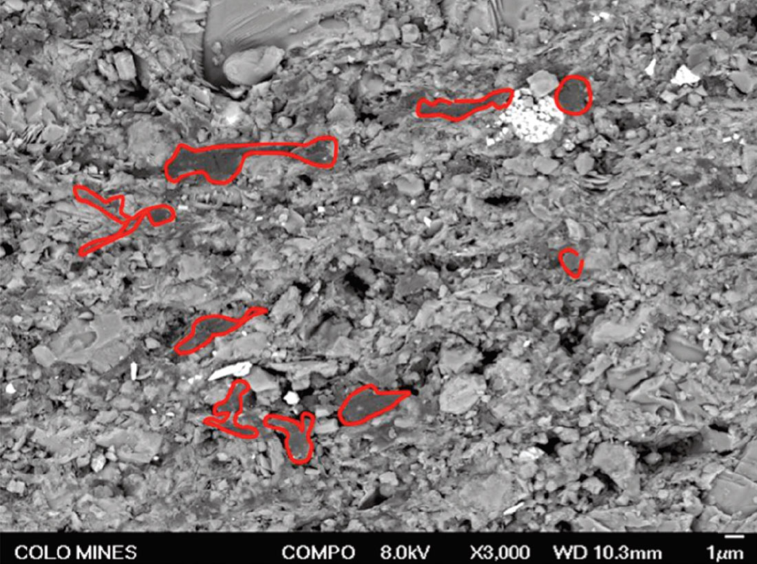
In this paper, we use pore size distribution data obtained from Mercury Intrusion Porosimetry (MIP) and Nitrogen gas adsorption. These data show presence of pores from a few nm diameter to a few μm. Such small pope sizes carry important implication about the flow regimes. Since velocity – porosity transforms use only the volumetric porosity information, the pore sizes need to be derived from additional data. Fluid pressure is a valuable parameter needed in the flow calculations. In this case, seismic data can be of enormous help. Both in the planning stage as well as during production, it is important to monitor and maintain reservoir pressures at a level that will ensure sustained production. Given the importance of flow characteristics, such information about pore size and fluid pressure is critical when assessing production scenarios as well as field development schemes.
Permeability and Flow Regimes
Gas flow in shale reservoirs is described by a combination of mechanisms acting at different scales (Javadpour et al., 2007; Javadpour, 2009: Wang and Reed, 2009; Freeman, 2010; Ozkan et al., 2010. These are:
- Desorption from kerogen and clay surfaces, and subsequent surface diffusion of the adsorbed gas molecules under a pressure gradient.
- Knudsen diffusion and slip flow in micropores, and
- Darcy flow in larger meso- and macropores.
In this paper, we will limit our discussion to the Knudsen diffusion, slip and Darcy flow mechanisms. Flow of fluids in rocks is generally modeled using Darcy’s equation, which is also known as advective flow. Flow of gases in tubes (including capillaries) is described by Hagen-Poiseuille equations with no-slip boundary conditions. The no-slip boundary condition indicates viscous bonding of fluids to the wall and is modeled by assuming the particle velocity to be zero at the wall of the pipe (or pore).
As the characteristic length (characteristic length is dimension that defines the scale of a physical system, and for porous media, characteristic length most commonly used is the pore-diameter) of the physical system decreases, the assumption of standard continuum approach falls apart. The dimensionless Knudsen number (Kn = λ\Rh, where λ is the mean free path of the gas, i.e. the average distance between two consecutive molecular collisions, and Rh is the characteristic pore diameter) is used to determine the degree of appropriateness of applying continuum approach. For Kn < 0.01, the mean free path of the gas molecules is negligible compared to the characteristic dimension of the flow geometry (i.e. Rh parameter), the continuum hypothesis of fluid mechanics generally holds true. Rarefaction effects become important as Knudsen number increase and consequently the pressure drop and mass flow rate cannot be predicted from the continuum model of fluid flow (Hagen-Poiseuille’s equation or Darcy-like flow). At Kn > 10 the gas molecules collide with the flow boundaries more often than inter-molecule collisions. Thus the molecules move independently of each other and in this condition the gas composition have no importance. This flow regime is known as Knudsen diffusion or free-molecule flow.
The intermediate region in between 0.01 < Kn < 10 cannot be considered neither as a continuum flow nor a free-molecule flow. A further classification is done for that region is given by Karniadakis et al. (2005):
- Slip flow ( 0.01 < Kn < 0.1 )
- Transition flow ( 0.1 < Kn < 10
In the slip flow regime (0.01 < Kn < 0.1) the no-slip boundary conditions doesn’t hold true, and a layer of about one mean free path thickness, known as the Knudsen layer, starts to become dominant between the bulk of the fluid and the wall surface. This results in a finite particle velocity value at the wall, and the corresponding flow regime is known as the slip flow regime. In petroleum engineering literature, Klinkenberg applied this slippage condition to the flow of a gas in a porous medium to derive a first order correction for the gas slippage (Freeman, 2010). As we increase the Knudsen number, either by increasing the mean free path of gas (i.e. gas flowing at very low pressure) or decreasing the pore size, the contribution of the Knudsen layer increases. It goes to a transition flow and then finally to pure Knudsen flow. However, the limits of the Knudsen number for each flow regime is purely empirical and are based on pipe flow experiment and will vary for other geometries and surface roughness (Karniadakis et al., 2005). Another important point we have to remember, that these theories were developed to explain rarefied gas flows at very low pressure. These models are experimentally verified or developed for sub-atmospheric (near vacuum) pressures. In our application, the gas flow happens at much higher pore pressures. Hence one needs to make the assumption that physics of the system remains the same at high pore pressure and is governed by the Knudsen number or the ratio of mean free path of the gas at particular condition to the pore diameter (Javadpour, 2009).
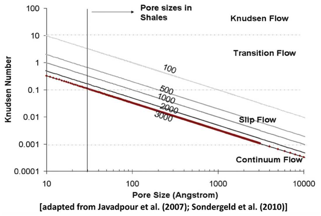
In this section, we will discuss the operational gas flow regimes that interests us. Figure 1c (adapted from Javadpour et al., 2007; Sondergeld et al., 2010) shows the Knudsen number as a function of pore size for different pore pressure ranging from 100 psi to 3000 psi. The Knudsen number increases with smaller pore size. The ranges of pore sizes in shales are shown in the figure. In Figure 1c, the line is drawn on the basis of the experimental data of compacted clay pellets obtained from N2 adsorption experiment. Figure 1c reveals that the dominant types of gas flow in those mesopores of clays are slip-flow and transition-flow.
Under high reservoir pore pressure, the Knudsen number indicates that pure Knudsen flow seems to be unlikely; it is rather expected to fall in the transition between Knudsen and Poiseuille flows (slip-flow and transition flow regimes). The pore pressure and the pore sizes are too large for pure Knudsen flow. The contribution from diffusion flow to the total flow will be more important when gas flow experiments are conducted under lab conditions. Current GRI technique measures gas permeability in crushed samples using pulse-decay techniques at STP. The equations for obtaining permeabilities assumes Darcy-like flow and do not account for slip, transition flow regime and associated diffusion effects. The diffusion effects needs to be modeled while measuring permeabilities in lab and should also be accounted for while extending the studies to reservoir conditions.
Historically, the slip flow and transition flow regime have being modeled as a combination of Knudsen flow and Poiseuille flow. Klinkenberg gave a first order approximation by suggesting simple addition of Knudsen and Poiseuille flow constants. Javadpour (2007) suggested similar approach of addition of Knudsen flow constant and Poiseuille flow constant multiplied by some factor to account for factors like wall smoothness. Karniadakis et al. (2005) suggested a unified equation to model the entire flow regime where the addition of Poisuelle flow constant and Knudsen flow constant multiplied by factors to account for rarefaction of gas and slip coefficient. Schofield et al. (1990) used a two-parameter semi-empirical equation combining the two flow constants to explain experimental data of gas flow through microporous membrane. All of these studies show that the transition regime of the gas flow can be modeled as weighted contribution of pure Knudsen flow and pure Poiseuille flow. In the following sections, we will show the relative contribution of Knudsen flow and Poiseuille flow as functions of pore size and pore pressure.
Modeling Gas Flow Regime in Shales
In this section, we will try to understand the control of pore-sizes on the flow regimes of gas. In the next section, the different flow regimes are discussed. A general equation of flux for gas permeation through porous media can be written as:

where, J is the mass flux per unit area, ΔP is the pore pressure gradient across the sample with thickness L and K is the mobility constant. Several processes are being described to the mass transport of gases. If the pore-width is large relative to the mean free path of the gas molecules (at high pore pressures and large pore radii), there are two major types of mass transport mechanisms. If a total pore pressure gradient exists, mass transport may take place as a result of Poiseuille or forced flow. If a partial pressure gradient exists, mass transport may take place as a result of molecule-to-molecule collision (molecular diffusion or Fickian diffusion). Fickian diffusion is not applicable for single-phase gas flow as the partial pressure will always be equal to one. Another important mechanism is surface diffusion which works for an adsorbed gas on the pore walls but in this case we are not considering this particular phenomenon. If the pore-width is small relative to the mean free path, mass transport occurs as a result of molecule-to-wall collision in the presence of either a total pressure or a partial pressure gradient (Knudsen diffusion or molecular flow).
Equation 2 (Hagen-Poiseuille flow equation) describes the advective flow of gas through a capillary pipe which occurs under total pressure gradient.

where, J is the mass flux, r is the pore radius, R is universal gas constant, M is the molecular weight of the gas, T is the temperature. For tortuous porous media, the equation becomes

The porosity φ of the porous media restricts the cross-sectional area available for transport. A second factor called tortuosity, τ accounts for the increase in the path length which the gas molecule flow. The ratio ‘φ/τ is also called the obstruction factor. These obstruction factor combined with the characteristics radius of the pores in the porous media gives the permeability k

Then Equation 3 becomes

The term ‘MP/RT’ represents the density of an ideal gas. For real gas, the gas-deviation factor needs to be added. Equation 3 can be written in the following form with the oil-field units

where, JP is mass flux in lb/ft2/Day, k is the permeability of the porous media in Darcy, η is the viscosity of gas in centipoise, P is the average pressure in psi, T is the temperature in Rankine, R is the universal gas constant (and is equal to 10.731) and L is the length in ft.
At low pressure, collisions are dominantly between molecules and the walls, and the free path is restricted by the geometry of the void space. In this regime, termed Knudsen diffusion, the flux depends only on the density gradient of the gas and can be written as

Note equation 7 has the same form as Fick’s diffusion equation. DK is the Knudsen diffusion coefficient of gas and it is different from Fickian diffusion coefficient. Knudsen diffusion coefficient DK is proportional to the mean velocity of the gas. In a long, straight, circular capillary of radius r < λ, the diffusion coefficient is given by

Where v is the mean molecular speed of the gas given by v=8RT πM and ‘φ/τ’ is the obstruction factor modification for porous media. DK is also self-diffusion coefficient and equation 8 shows that DK is independent of pressure and changes as T1/2 with temperature. From equation 7 and equation 8, we get the following equation assuming isothermal conditions (T constant)


Comparing equation 11 and equation 3 with equation 1, the flow constant can be obtained for Knudsen flow and Hagen-Poiseuille flow as follows:

where, KK is the flow constant for Knudsen flow and

where, KP is the flow constant for Poiseuille flow. It should be noted that the Knudsen flow constant KK is independent of pressure while the Poiseuille flow constant is dependent on pore pressure. Comparing the flow constants KK and KP at different pore radius r will give us an idea about the relative importance of these flow regimes and their contribution to total flux.
Flow Constants for different pore-sizes
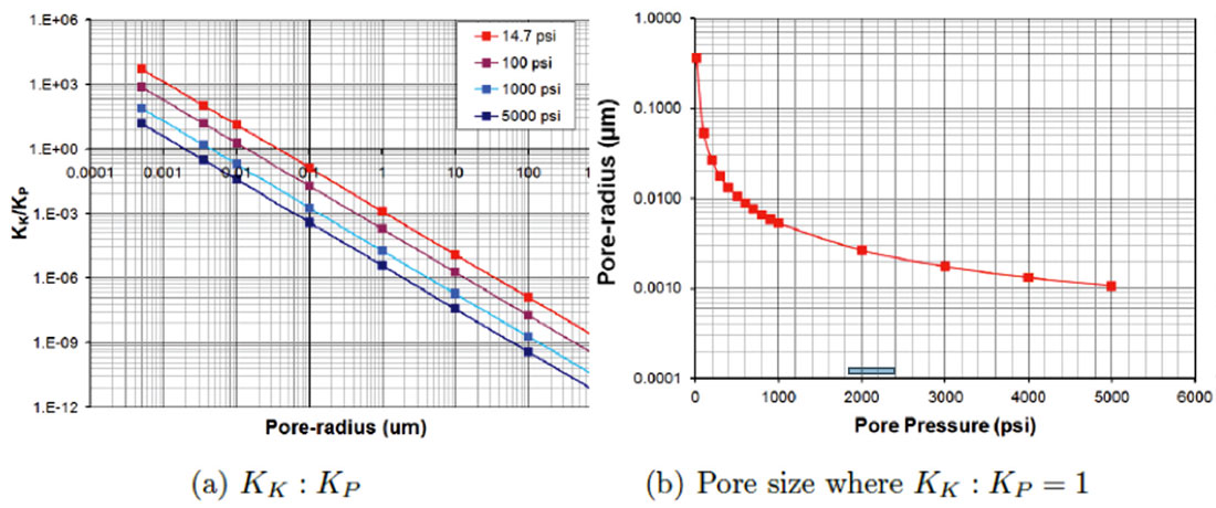
Figure 2 shows the flow constants as a function of pore radius at different pore pressures. The porosity φ and the tortuosity τ values used are typical for shales (0.08 for φ and 3.00 for τ). At low pore pressure (14.7 psi) Knudsen flow will dominate over Poiseuille flow for pore-sizes below 0.2 μm. Since KK is independent of pore pressure and KP is directly proportional to pore pressure, at higher pore pressures, Poiseuille flow dominates over Knudsen flow.
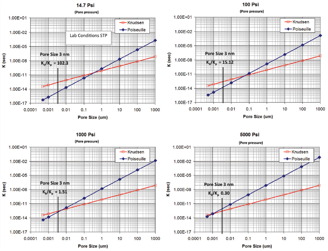
The pore size at which KP dominates over KK moves towards smaller pores as pore pressure is increased. An example of the relative dominance of Poiseuille flow and Knudsen flow for smallest pore-sizes revealed in shales (3 nm) is shown in figure 2. The ratio of KK to KP decreases from 102.3 to 0.3 as pore pressure increases from 14.7 psi to 5000 psi. Figure 3a shows the relative dominance of Knudsen flow over Poiseuille flow for all poresizes at different pore pressure. Figure 3b shows the pore-sizes at which contribution of Knudsen flow is equal to the contribution of Poiseuille’s flow as a function of pore pressure.
Flow Constants from pore-size in shales
The above plots suggest that flow from larger pore throats generally follow Darcy flow but contribution from Knudsen flow will be important in flows through the small pores. Shales are lithified clays, which constitute more than 50% of the rock with organic materials (kerogen) and detrital grains present in varying amounts. The presence of these extremely small pores (generally associated with clays and the kerogen) are documented in several studies. Shale gas reservoirs can possess a high degree of heterogeneity and widely varying porosity distributions. High pressure mercury injection data for Beaufort- MacKenzie Basin shale samples (Conell-Madore and Katsube, 2006) suggest a pore-size distribution with mode 2.5-25 nm. The pore-size distribution from Conell-Madore and Katsube (2006) is used to model the contribution of Knudsen flow and Poiseuille flow for shale systems. The pore-size-distribution data are modeled assuming the pores to be a bunch of straight capillary tubes and the Knudsen flow constant and the Poiseuille flow constant are calculated using the following formulae:


where, KK is the flow constant for Knudsen flow, r is the range of pore-sizes, φi is the partial porosity for the pore-size ri and τ is the tortuosity (1 in this case) and KP is the flow constant for Poiseuille flow.
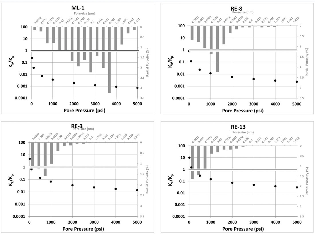
Figure 4 shows the ratio of Knudsen flow over Poiseuille flow for four shale samples from the Connell-Madore and Katsube data with different pore-size distributions (plotted in the background). ML-1 have the highest porosity (21.30%) and largest relative proportions of macropores. RE-8, RE-3 and RE-13 have respectively more relative proportions of mesopores. The contribution of Knudsen diffusion over the Poiseuille flow increases from ML-1 to RE-13. For the finer pored shales, under reservoir conditions (around 1000-2000 psi pore pressure), there is a significant contribution of Knudsen diffusion to the total flow.
Discussion
The pore-size dimensions of these shale systems can vary widely, potentially ranging from 10 nm to 5 μm. The distribution of pore throat sizes will vary reservoir by reservoir. The results of this modeling show that the ratio of Knudsen flow constant to Poiseuille (Darcy) flow constant increases sharply as pore sizes reduce to smaller than 100 nm. Also, Knudsen diffusions contributions to flow increase as pores become smaller. The modeling results specifically shows that presence of small micro and mesospores is important but more importantly the relative abundance of these small pore sizes compared to large pore sizes control the gas flow behavior of shales. This model provides a strong basis for future work, such as to incorporate and account for Knudsen diffusion while measuring permeabilities of shale in laboratory conditions and also in reservoir modeling in shales. We will also investigate the applicability of pore-size distribution data for shales to make qualitative and quantitative prediction of flow properties of shales.

Acknowledgements
The authors gratefully acknowledge the OCLASSH consortium for funding this project. Other thanks to the Fluid / DHI Consortium at Colorado School of Mines.


Join the Conversation
Interested in starting, or contributing to a conversation about an article or issue of the RECORDER? Join our CSEG LinkedIn Group.
Share This Article