Summary
This paper compares conventional 3D seismic survey design with the 3D symmetric sampling approach. Conventional survey design focuses on midpoint gathers, whereas the 3D symmetric sampling approach focuses on shot and receiver gathers. The differences are illustrated by the way in which obstacles are tackled: skidding and off setting as in the conventional approach, or smooth acquisition lines as promoted in 3D symmetric sampling. The latter approach allows successful prestack noise suppression and reduces prestack migration artefacts to a minimum.
Introduction
When designing a 3D seismic survey the first choice to be made is the type of acquisition geometry. There are three major types (Vermeer, 2002): parallel geometry (source lines parallel to receiver lines), orthogonal geometry (source lines orthogonal to receiver lines), and areal geometry (sparse grid of receivers combined with dense grid of sources). Other geometries that have been or are being used are: brick-wall geometry (source lines and receiver lines form a brick-wall pattern), slanted geometry (source lines non-orthogonal to receiver lines) and zigzag geometry (two families of source lines making angles of 45º and 135º with the receiver lines).
Once a type of geometry has been selected, the parameters of the geometry have to be decided upon. Geometry selection and parameter choice may be carried out using conventional survey design methods such as described in Stone (1994), Cordsen et al., (2000), Musser (2000) and Donze and Crews (2000) or according to 3D symmetric sampling principles described in Vermeer (2002). In earlier papers I have also extolled the virtues of the 3D symmetric sampling approach, but in this paper I will contrast these with the disadvantages of the conventional approach.
This paper starts with a description of conventional survey design and the rationale for this approach. In the second part I will review the benefits of the 3D symmetric sampling approach and the failure of the conventional approach to meet basic criteria of spatial continuity, optimal noise suppression and imaging without artefacts.
Conventional 3D seismic survey design
Essentially, the conventional approach to 3D seismic survey design is a straightforward extension of the 2D stack-array approach (Anstey, 1986) to 3D. In the stack-array appro a c h the combination of geophone array and stack (together called stack-array) forms a very good means of suppressing the ground roll. A prerequisite is equal sampling of shots and receivers for centre-spread land data acquisition and shot intervals half the receiver station intervals for marine end-of-spread acquisition. The stack-array approach leads to common midpoints (CMPs) with a regular distribution of offsets and a very good stack response (see Figure 1).
Conventional survey design aiming to copy the advantages of the 2D stack-array to 3D puts considerable emphasis on a regular offset distribution in each bin, and on a concentration of midpoints in the bin centres. For parallel geometry it is no big problem to satisfy stack-array criteria. Each combination of a regularly sampled source line and a regularly sampled receiver line parallel to the source line produces a regularly sampled midpoint line with a regular (absolute-) offset distribution. Depending on the distance between the two acquisition lines (the crossline offset), regularity of offsets will only be affected for the small offsets in general. Another geometry emulating the stack-array concept successfully with a regular offset distribution in each bin is the double-zigzag geometry (Wams and Rozemond, 1998).
However, applying stack-array principles to the design of orthogonal geometry meets major problems. In the early days of 3D seismic data acquisition it was soon realized that on land orthogonal geometry has considerable advantages in efficiency over parallel geometry. Yet, with a limited number of available channels the first orthogonal surveys had a very small aspect ratio (maximum crossline offset much smaller than maximum inline offset). This led to considerable pairing of offsets (the occurrence of two traces with nearly the same absolute offset) in each bin. The pairing of offsets had a negative impact on the stack response of such geometries resulting in serious acquisition footprints. Then it was discovered that some of this pairing of offsets could be done away with by choosing brick-wall geometry. It was also noticed that wide orthogonal geometries (maximum crossline offset about equal to maximum inline offset) produce a very irregular absolute offset distribution. For some geophysicists this was a reason to reject wide orthogonal geometries as not meeting the objective of a regular offset distribution.
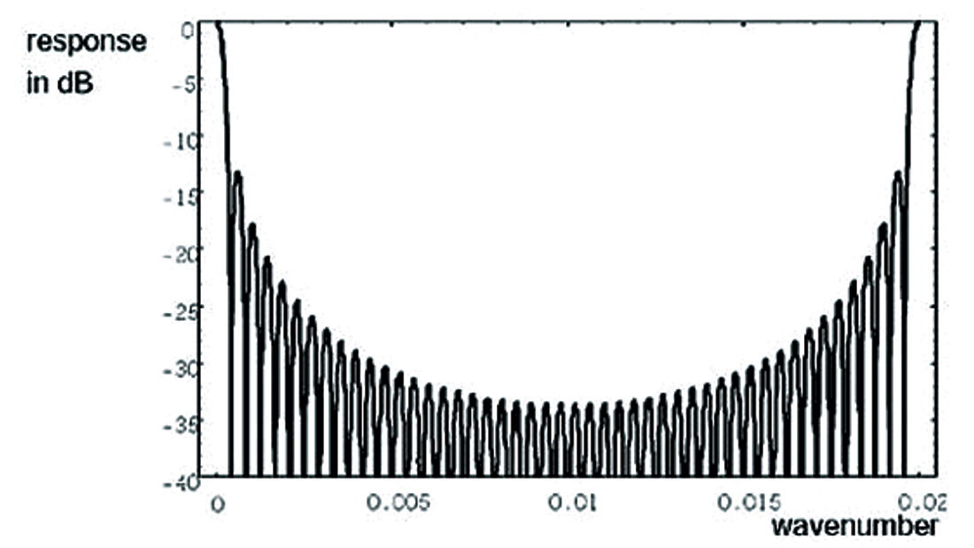
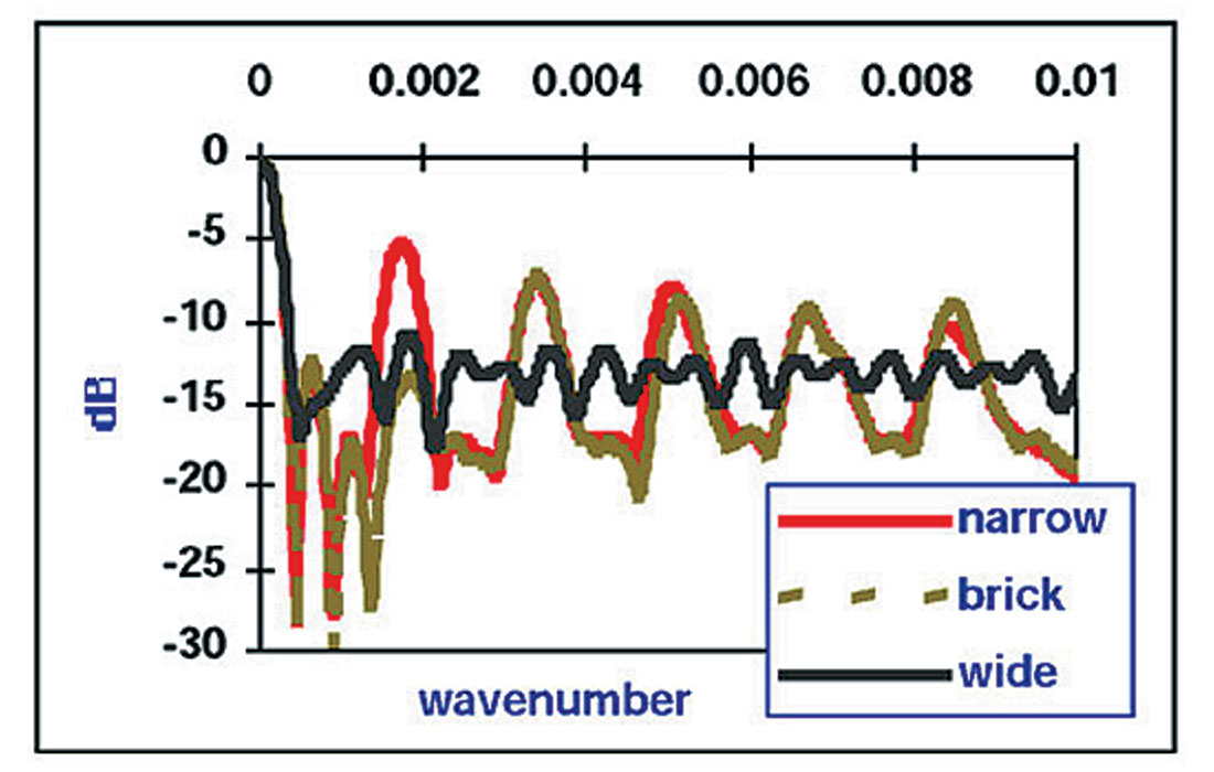
The question is: does a regular distribution of offsets always lead to the best stack response? The answer is no. In 2D, a regular offset distribution produces a peak in the stack response at k = 1/d, k wavenumber, d offset-interval of the traces in a CMP (see Figure 1). Noise with wavelength λ = d escapes suppression. This does not matter for high-fold 2D data, because there will be little energy at small wavelengths. However, in narrow orthogonal geometry, the pairing of offsets produces peaks in the stack response for longer wavelengths. On the other hand, in a wide orthogonal geometry, the absolute-offset distribution is more or less random, so that no wavelengths can escape suppression and there are no peaks in the stack response. This is illustrated in Figure 2, where the average stack responses of narrow orthogonal geometry, narrow brick-wall geometry and wide orthogonal geometry are compared with each other. Although the stack response of brick geometry is better than that of narrow geometry, it is still a lot worse than that of wide geometry.
Another focus of conventional survey design is the concentration of midpoints in the bin centres. This culminates in the skidding and offsetting rules as discussed in Donze and Crews (2000). If a shot cannot be placed at the nominal position, then it is allowed to deviate from that position by a little bit only, thus ensuring that all midpoints for that shot will be located in a quarter-binsize area around the bin centres. This shifting of the shot position is called skidding. If there is no position in that area where the shot can be placed, then the shot has to be shifted an integer number of receiver station spacings to the right or to the left of the shot line. This shifting of shots is called offsetting. And there are more rules for shifting shots if the simple offsetting does not produce a feasible location either (Donze and Crews, 2000), all focused on concentrating midpoints in bin centres.
The midpoint centring rule was very desirable in those days when the application of DMO was still a rarity, and prestack migration only existed in the minds of researchers. It prevented loss of high frequencies in stacking due to midpoint smear. However, those days are gone, midpoints have been relegated to what they should be: a means of bookkeeping in processing, and it has become much more important to look after successful imaging by DMO or by prestack migration. For optimal results, these imaging processes require input without any spatial discontinuities. This is the focus of 3D symmetric sampling.
The 3D symmetric sampling approach to survey design
Essentially, the symmetric sampling approach to 3D seismic survey design is a straightforward extension of the 2D symmetric sampling approach (Vermeer, 1990) to 3D. In 2D symmetric sampling the shot interval is equal to the receiver station interval because the properties of the common receiver gather are the same as those of the common shot gather due to reciprocity. Preferably, the shot arrays are equal to the receiver arrays. This sampling recipe leads to common receiver gathers that look like common shot gathers whereas both gathers are equally suitable to various prestack processing steps, such as (f, k)-filtering.
In actual fact, there is not all that much difference between Anstey’s stack-array approach, and the 2D symmetric sampling approach. (The hands-off acquisition technique proposed by Ongkiehong and Askin, 1988, is very similar as well.) It is more a matter of emphasis than of principle. However, this difference in emphasis leads to very large differences between the extensions to 3D. Actually, in 3D the difference becomes a matter of principle. Whereas conventional survey design is midpoint-oriented, 3D symmetric sampling focuses on the equivalence of common shot gathers and common receiver gathers (Vermeer, 2002).
This equivalence is particularly important in orthogonal geometry. In this geometry the shot lines play the same role in the crossline direction as the receiver lines in the inline direction. Therefore, for equal character and quality of crosslines and inlines it is important that sampling in both directions is the same. This means that not only the shot interval should be equal to the receiver interval, but also that the maximum crossline offset should be equal to (or at least not very different from) the maximum inline offset. In this way the common receiver gathers will be common shot gather look-alikes.
An immediate consequence of these 3D symmetric sampling rules is that brick-wall geometry is not an acceptable kind of geometry. Although the common shot gathers in this geometry will be nice and smooth in general, the common receiver gathers will consist of small pieces of shot line with jumps from one piece to the next, dependent on the bricking distance. This means that the common receiver gathers will show many spatial discontinuities, also in the coherent noise, which translate into serious migration artefacts in the crossline direction.
Similarly, avoiding obstacles by offsetting individual shots as in the Donze and Crews (2000) recipe leads to discontinuities in the common receiver gathers. These discontinuities can be avoided by considering the line along which the shots are being sampled. If this line is smooth, there will be no spatial discontinuities in the common receiver gathers. Hence, if a particular shot has to be moved due to the presence of an obstacle, it is likely that neighbouring shots will have to be moved as well to ensure smoothness of the shot line.
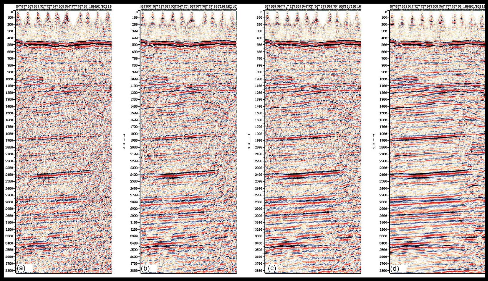
The recipe for smooth and continuous acquisition lines combined with a maximum crossline offset that is about equal to the maximum inline offset leads to the collection of well-sampled cross-spreads (Vermeer, 2002). These cross-spreads are in fact small 3D cubes that are eminently suited for 3D velocity filtering. Recent papers have demonstrated the power of 3D velocity filtering (Galibert et al., 2002; Girard et al., 2002; Karagül and Crawford, 2003). Figure 3 reproduces the example given in Karagül and Crawford (2003). There is no way one can achieve similar results with data acquired with brick-wall geometry. Actually, those results are sufficiently successful to allow lower fold-of-coverage as noise suppression does not need to rely on the stacking process anymore. Note however, that these results are strongly dependent on the sampling intervals. The better the sampling of the noise, the more noise and signal are separated in the (f,k,k)-domain, and the better the noise can be removed.
The 3D symmetric sampling approach minimizes the number of spatial discontinuities. The equal character inline and crossline ensures imaging with minimal artefacts. Prestack migration is highly vulnerable to spatial discontinuities. Clearly, the crossline direction is as important to the imaging process as the inline direction and should not be spoiled by ill-advised attempts to force midpoints into bin centres.
Examples
It is interesting to compare maps of data acquired with the conventional approach to maps of data acquire d with the 3D symmetric sampling approach. Figure 4 reproduces a map shown earlier in a paper on nearsurface issues for 3D survey design (Criss et al., 2002). It shows a brick-wall geometry that has been distorted largely by offsetting and a little bit of skidding. Although each shot sees nice and regular receiver lines leading to nice and regular common shot gathers, the distribution of shots is a real mess, leading to poor crosslines.
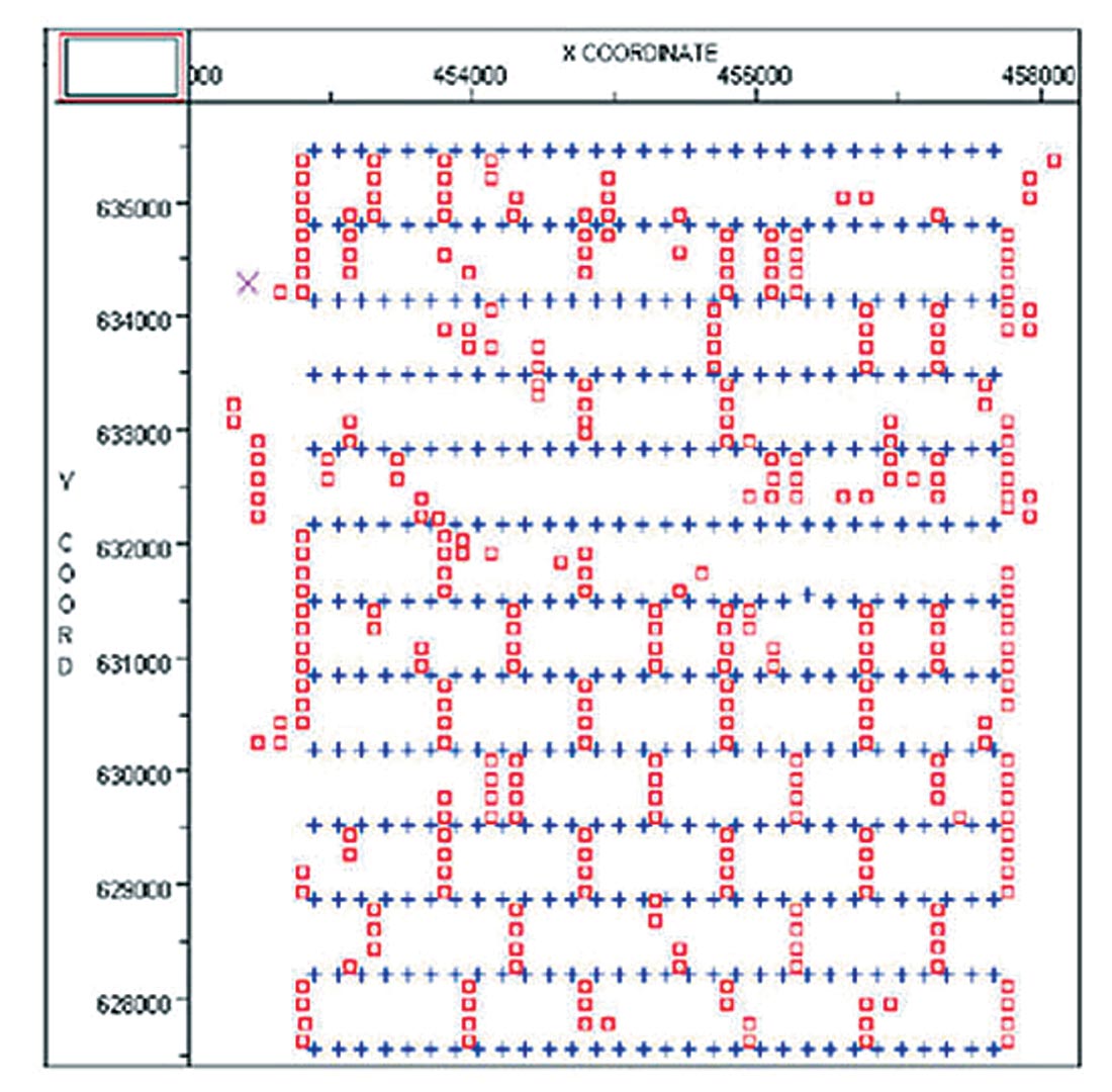
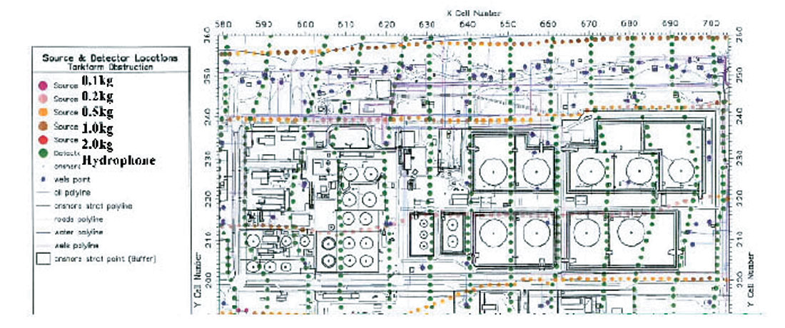
Figure 4 may be compared with Figure 5, copied from a paper by Wood et al., (1999). The survey area abounds with obstacles, as the oil terminal in the figure, the oil refinery to the South, and the city of Seria to the West are all sitting on top of the very oil field for which a more detailed structural picture is required. Despite all these obstacles, continuity and smoothness of both shot lines and receiver lines was maintained throughout. This contributed to the very satisfactory results of this high resolution survey (Wood et al., 1999).
Conclusions
Conventional 3D seismic survey design focuses on regular offset distributions and on midpoints in bin centres. It was shown that this focus is based on too strict an extension of the 2D stack-array approach to 3D. It leads to the treatment of shots as individual entities, rather than as samples of a shot line. This results in spatial discontinuities, in particular in the common receiver gathers. These spatial discontinuities prevent proper prestack noise suppression and lead to migration smiles in the crossline direction.
The 3D symmetric sampling approach to 3D survey design focuses on spatial continuity. In particular if an acquisition line cannot be sampled as planned, the line has to be moved in a smooth way rather than moving individual shots or receivers. This approach leads to common receiver gathers that are common shot gather look-alikes, thus producing data with the same character and quality in the crossline direction as in the inline direction. 3D symmetric sampling allows successful prestack noise suppression by 3D velocity filtering and reduces prestack migration artefacts to a minimum.

Acknowledgements
This paper is a modified version of my 2003 SEG paper with the same title.


Join the Conversation
Interested in starting, or contributing to a conversation about an article or issue of the RECORDER? Join our CSEG LinkedIn Group.
Share This Article