Background
In near surface environmental geophysics, the provider of such services will often propose that carrying out such work will save the client money in the overall project. Occasionally, and often in direct correlation with the quality of the work, such services result in increased budgets over the short term. For instance, a well done terrain conductivity survey of an abandoned one hectare well site with a history of salt water spills may map a few hundred square meters of contaminated soil, but may also find a groundwater contaminant plume covering several hectares, and lead to a large groundwater sampling program. Or, a borehole geophysical logging program in a poor producing water well may clearly show that the screen is not properly placed, thus requiring the drilling and completion of a new water well.
Nevertheless, carrying out a geophysics program in advance of horizontal drilling beneath a proposed pipeline river crossing will invariably save the client time and money. The cost of a geophysics program is usually only a few percent of the cost of a horizontal drilling program (Figure 1). When geologic conditions present numerous unknowns, horizontal drilling companies will present significantly increased budgets to provide for contingencies that may be required when geologic conditions change while drilling. The more time that is required for the horizontal drill, the longer it will take to get an oil or gas well tied in. A geophysical program may also show that horizontal drilling at a certain crossing, in fact, is not feasible, and an open cut or rerouting should be considered.
Most important to consider, though, is the reduced environmental impact that will often result from a pre-drill geophysics program. Incised channels, unexpectedly thick gravels, and heavily fractured bedrock may all result in drilling mud losses to rivers and streams. This occurrence may have particularly catastrophic consequences in sensitive fish spawning creeks and rivers. Inadequate bedrock cover may eventually result in pipeline exposure and rupture during the spring runoff. Inadequate cover on a steep slope may eventually lead to a pipeline rupture during an avalanche or other mass wasting event. In particularly sensitive situations, Alberta Environment may simply require that all possible precautions be taken as related to horizontal drilling.
Typically, pipeline engineers and horizontal drillers will have the same four questions: 1. At what depth is the top of bedrock? 2. What lithology is the overburden? 3. What lithology is the bedrock? 4. Is bedrock fractured? Irregular bedrock relief may lead to the horizontal drill intersecting overburden. Should bedrock be too deep, horizontal drilling may be impractical. Granular overburden creates challenges for mud containment. Highly permeable bedrock may offer no better containment than granular overburden. Similarly, highly fractured or karsted bedrock may create high permeability zones in lithologies that normally have very low hydraulic conductivities.
Geophysical Methods
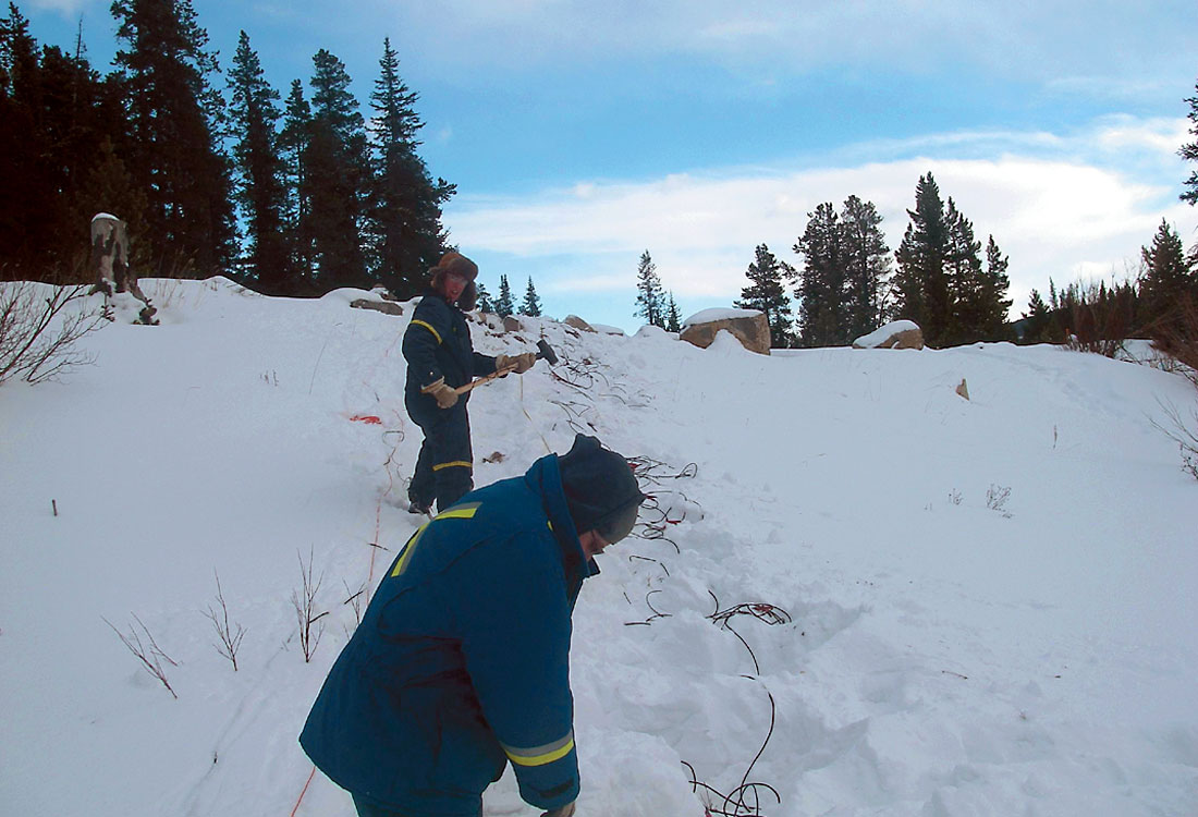
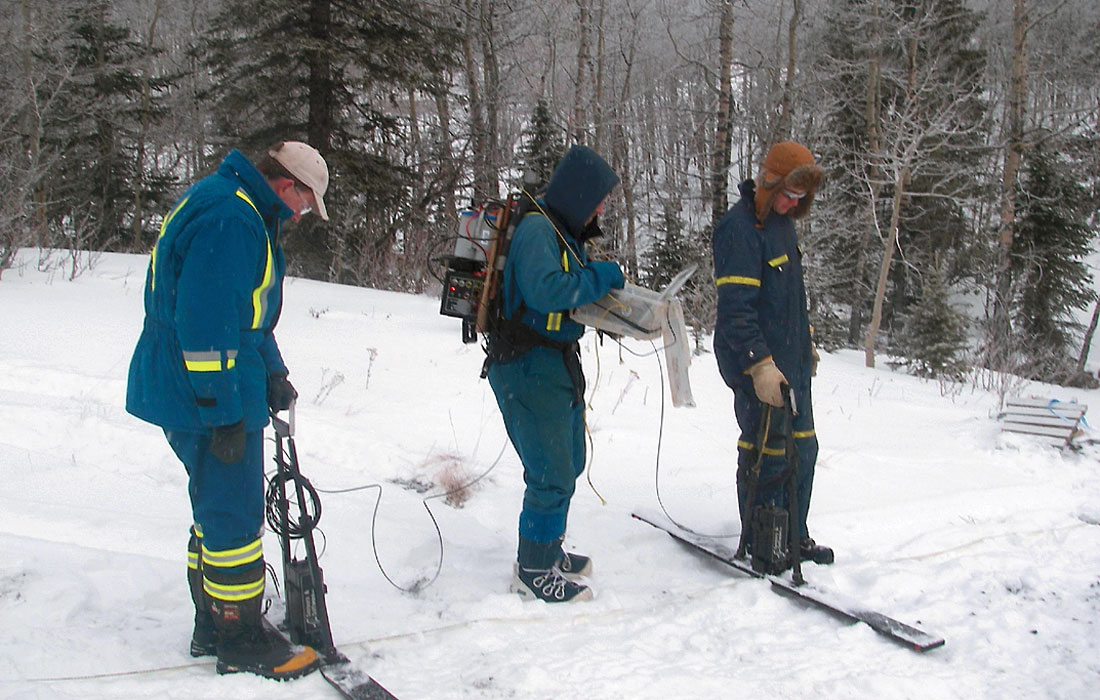
While most geophysical methods may offer some insight into answering the above four questions, we have found that four methods are particularly useful, and are routinely applied. These include electrical resistivity tomography (ERT), seismic refraction, ground penetrating radar (GPR), and borehole geophysics. Figures 2, 3, and 4 show the surface methods being applied. That multiple techniques may be required is an outcome of the inherent ambiguity often encountered with the total reliance on any single technique. For instance, water saturated sands and gravels may have similar resistivities to either sandstone or limestone; however, competent bedrock will show much faster velocities in a seismic refraction survey than very slow saturated granular material, and even slower unsaturated granular material. Similarly, both a clay till and shale bedrock will strongly attenuate radar waves, but unweathered shale bedrock will likely have a lower electrical resistivity than overlying till, and invariably have a faster acoustic wave velocity.
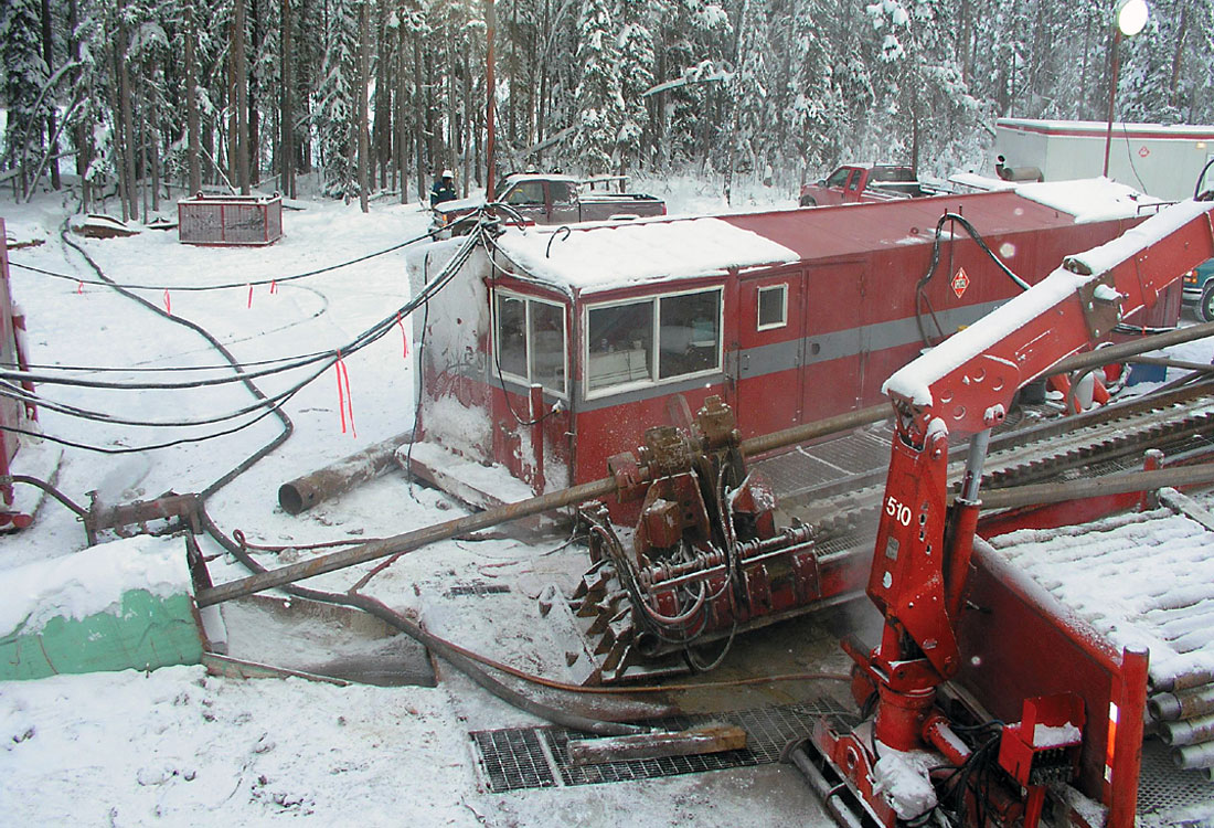
Regardless of the quantity and quality of the geophysical data, some drilling control is always recommended to “truth” the geophysical interpretations. For a river crossing, ideally, four drill holes are provided, one at the horizontal drill entry point, a second at the exit point, a third on one river bank, and a fourth on the other river bank. The surface geophysics then ties into the boreholes and describes subsurface conditions between boreholes. Boreholes are typically geophysically logged with induction conductivity and natural gamma tools for lithology, and a borehole imager for bedrock fracture identification and description. Due to difficult access (canyons, steep slopes, road conditions, etc.) or budget constraints, it is rare that four boreholes are actually provided. However, at least one borehole to truth the geophysical interpretations should be mandatory.
Examples
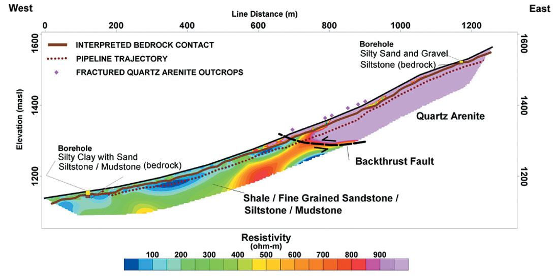
The utility and applications of the above geophysical methods can best be described though examples. ERT is a 2-D electrical technique for imaging “true” resistivities in cross-section. The results of a 1.3 kilometre (km) survey imaging to a depth of 50 m below ground surface (mbgs) are provided in Figure 5. Clearly evident is the backthrust fault where the lithology changes from the moderate resistivity (<250 ohm-m) and easily drilled argillaceous rock (green and blue) to the very resistive (>1,000 ohm-m) and extremely difficult to drill quartz arenite (pink).
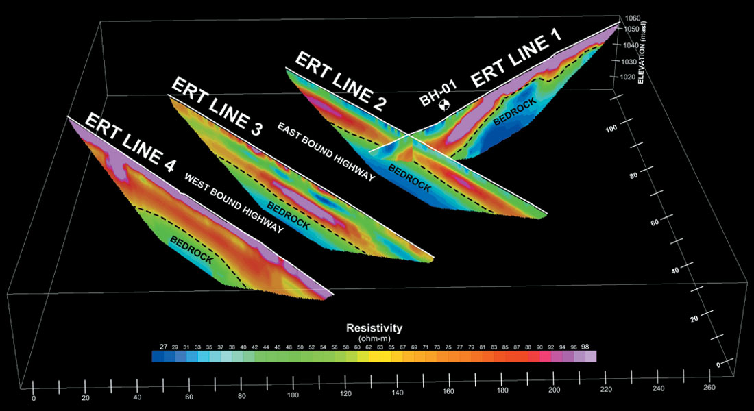
In Figure 6, six ERT sections have been compiled to image the depth to bedrock and continuity of granular material at a proposed horizontal drill under a large Alberta river. The granular overburden is highly resistive, while bedrock is of moderate to low resistivity. Ground “truthing” was provided by one borehole on each bank of the river. A short section of seismic refraction was also shot to gain confidence in the ERT bedrock pick. The borehole gamma log of Figure 7 supports the bedrock intersection imaged in the ERT and seismic refraction surveys, while providing additional lithologic information not available from the surface geophysical surveys on their own. The marine ERT data were collected with the aid of a marine streamer in a similar manner as would be done for a marine seismic survey. A plan view of the survey program is provided in Figure 8.
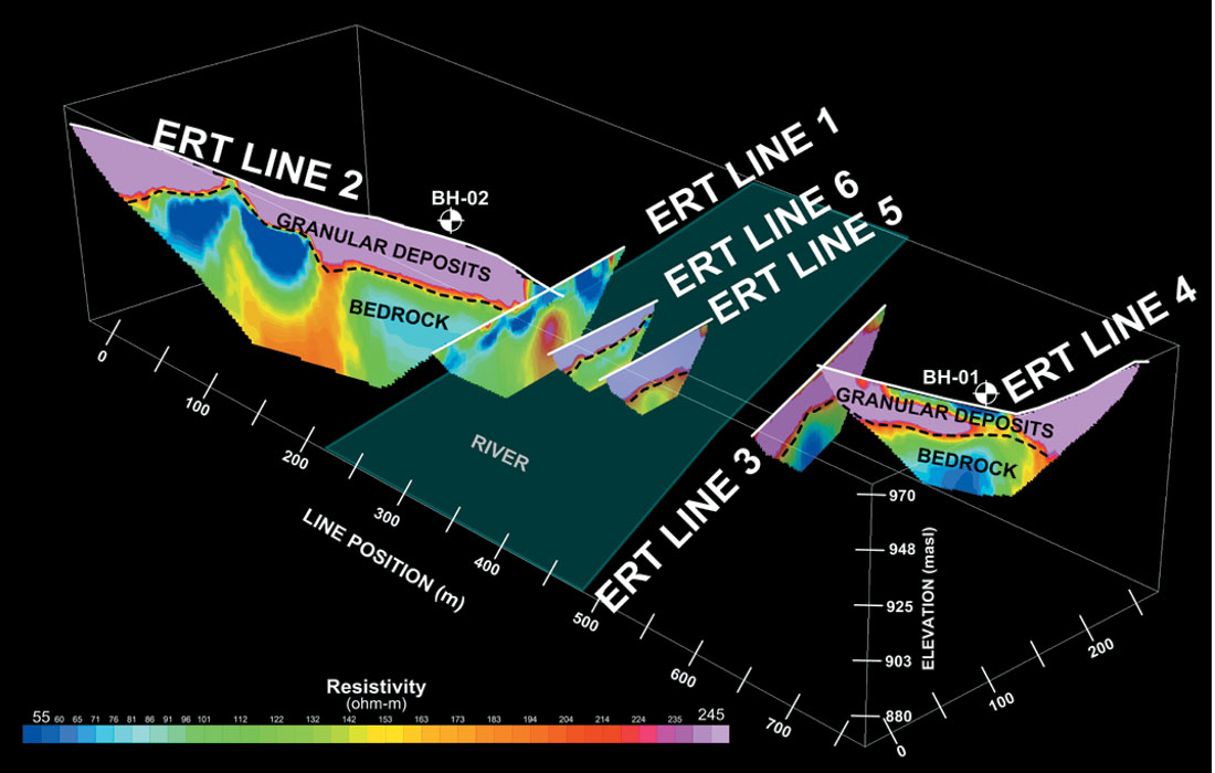
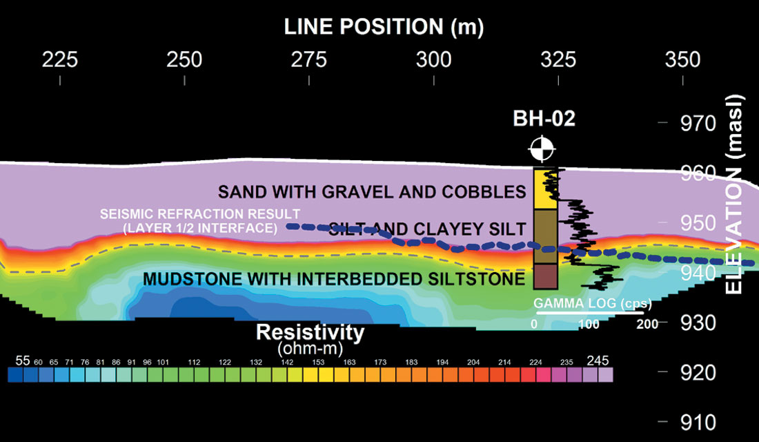
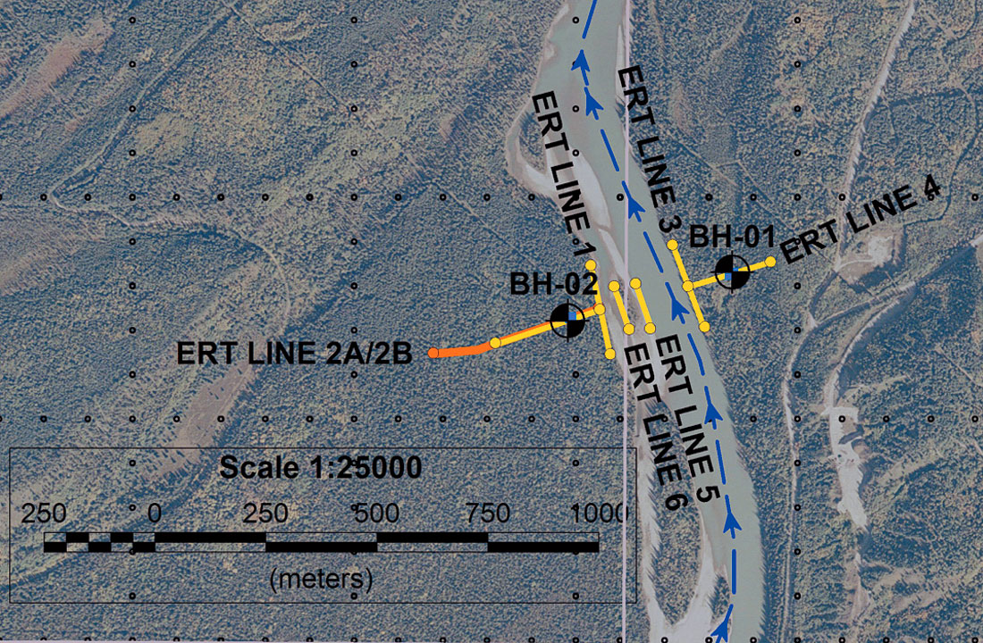
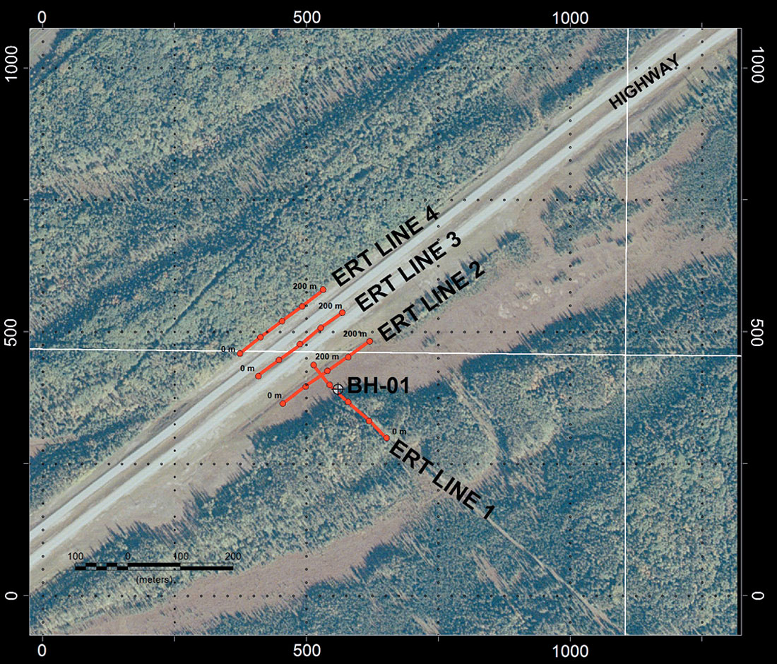
Figure 9 shows the plan view of an ERT program similar to that of Figure 8, but beneath a highway instead of a river. The results of the four ERT sections are presented in Figure 10. The depth to bedrock and the largely granular nature of the overburden are evident.
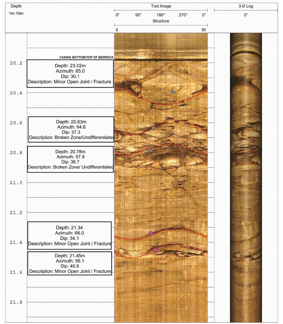
Despite theory that says otherwise, in practice, surface geophysical techniques are severely challenged in providing useful fracture characterization information in many sedimentary rock environments. Similarly, even coring of boreholes can provide ambiguous information regarding fracturing as the coring and core handling processes themselves may create fractures or alter the geometry of existing fractures. Nor is 100% recovery of oriented core a reasonable expectation under most circumstances. Hence, we have found that digital optical borehole imaging (OBI) of bedrock is the preferred method of in situ fracture identification, fracture aperture calculation, and fracture dip and azimuth measurements (Figure 11). An example of such a log collected at a river crossing investigation is provided in Figure 12. It is clearly evident that the weathered bedrock surface is heavily fractured, while fracture density rapidly decreases with depth. The fracture orientations largely correlate with the bedding planes. Fracture aperture, azimuth, and dip are readily measured.
Conclusion
Using near surface geophysics alone to predict subsurface conditions along a proposed horizontal drill path is not an exact science, but neither are geotechnical borehole investigations on their own. The challenges are most notable at large river crossings where geotechnical drilling information cannot be obtained from beneath the river, bedrock lithologies may change dramatically from one bank of the river to the other, incised channels may intersect the proposed horizontal drill path, bedrock fracturing may provide a pathway for drilling mud, and granular overburden may be of considerable, but variable thickness. 2-D resistivity, seismic refraction, and g round penetrating radar together will usually provide reasonably accurate delineation of depth to bedrock and identification of overburden and bedrock lithologies. Optical borehole imaging in geotechnical boreholes provides in situ measurements of fracture densities, apertures, azimuths, and dips. Geophysical logging of the geotechnical boreholes provides precise lithologic contact information as well as a physical properties bridge between the surface geophysics and the geotechnical borehole descriptions. Geotechnical borings provide essential “truthing” of the geophysical interpretations.


Join the Conversation
Interested in starting, or contributing to a conversation about an article or issue of the RECORDER? Join our CSEG LinkedIn Group.
Share This Article