Introduction
Zoeppritz’s equations with ray tracing and full elastic wave equation with finite difference method (FDM) are two most commonly used techniques in AVO modeling. The main difference between these two techniques is the former calculates the primary-only reflectivities and the latter calculates particle displacements in subsurface. Zoeppritz modeling has the advantages of being fast and easy for identifying primary reflections. Elastic wave equation modeling, however, accounts for direct waves, primary and multiple-reflection waves, converted waves, head waves, as well as diffraction waves. It overcomes the shortcomings of the ray tracing approach that breaks down in many cases such as at the edges where the calculated amplitude is infinite or in the shadow zones where the amplitude is zero. Baker (1989) summarized the advantages using wave equation modeling in the cases of complex geology or complex wave phenomena as: a) automatic generation of diffractions, critical refraction and multiples; b) more accurate amplitudes and waveforms, especially in the presence of small structures and thin beds; and c) no missing of seismic events regardless of complexity. For structured plays, elastic wave equation modeling is especially useful in both imaging and AVO analysis.
Based on Zoeppritz modeling and elastic wave equation modeling, different methodologies in AVO modeling are developed to take into account of the issues in association with data acquisition, processing and interpretation. This paper, Part 2 of AVO Modeling in Seismic Processing and Interpretation, reviews Zoeppritz equations and elastic wave equations and discusses pros and cons of the methodologies in AVO modeling.
Zoeppritz equations and elastic wave equations
For a two-layer interface, in total sixteen Zoeppritz equations describe the energy partitioning of reflected and transmitted waves (Aki and Richards, 1980). The commonly used equations are: an incident P-wave is reflected as a P-wave (P-P) or a converted S-wave (P-SV). Table 1 lists these two equations. Where a1, b1 and r1 are P- and S-wave velocities and density for the layer above and a2, b2 and r2 are for the layer below; i1 and i2 are reflected and transmitted angles for P-wave; and j1 and j2 are the reflected and transmitted angles for S-waves. It can be seen that they have complex forms.
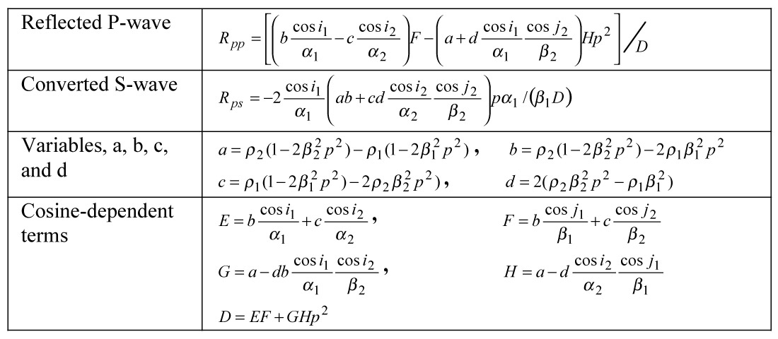
In AVO modeling, Zoeppritz equations are used to generate exact solutions. AVO attributes are then calculated based on the simplified Zoeppritz equations that have been discussed in Part 1 of this paper (Li et al., 2003). In AVO attribute inversion, least squares method (L2) or absolute deviation minimization (L1) methods that fits the observed amplitudes to a linear equation are often used. For example, Shuey’s equation yields estimates of zero-offset reflectivity and gradient; and Fatti’s equation gives estimates of P- and S-reflectivities.
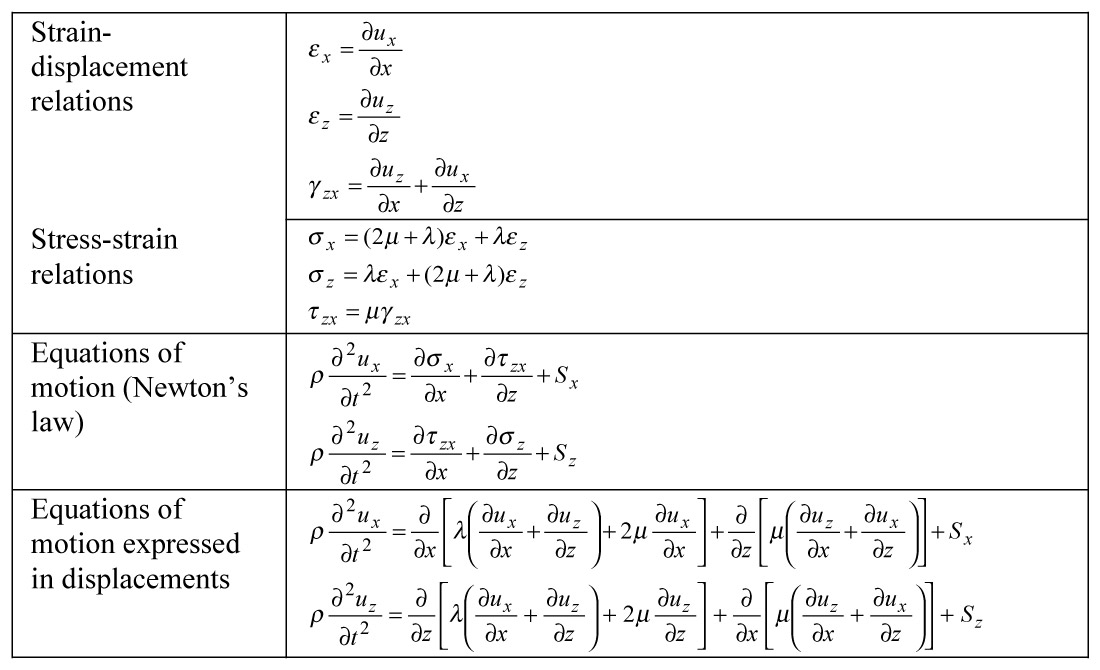
Table 2 lists 2-D elastic wave equations. The equations of motion are derived first based on Newton’s law and expressed by stress components σx, σz and τzx. The form expressed by displacements, ux and uz is derived through using strain-displacement relations and stress-strain relations. In Table 2, Sx and Sz are source components. To numerically stimulate wave propagation in subsurface, the equations of motion are often transformed into finite difference equations with given boundary conditions. Kelly et al. (1976) gave a detailed description of 2-D finite difference equations. For 3-D case, one may refer to the finite difference equations given by Jastram and Tessmer (1994). In finite difference calculation, explicit scheme approach is often used. It calculates particle motion for a space location at an advanced time exclusively from the motion that is already determined for previous time. In AVO modeling, a single shot gather with a flat-layered model can be generated for the cases where the structural effect is not the major concern. In structured areas, a series of shot gathers are generated based on a geological model and these shot gathers are the input for further processing.
AVO modeling methodologies
Different approaches can be taken in conducting an AVO modeling in terms of the objective. Single interface modeling, single gather modeling, 2D stratigraphic modeling and 2D elastic wave equation modeling are most commonly used and are to be discussed.
1. Single interface modeling
One of the advantages of single interface modeling is freedom from tuning. This method is often used to show theoretical AVO responses. For example, Rutherford and Williams (1989) used this method to classify AVO types for a shale-gas interface, and Shuey (1985) used it to compare between the exact Zoeppritz solution (Aki and Richard, 1980) and the solutions from his simplified equations. To demonstrate single interface AV O modeling three examples are selected and shown in Figure 1. Figure 1a shows the AVO responses for a case of shale overlying porous gas sand; where the results from two- and three-term Shuey’s equations are compared to evaluate the error introduced by the truncation of the third term. The maximum and minimum amplitude locations and inflection point location as indicated are calculated from the three-term equation. Figure 1b shows an example of the anisotropic effect of shale for a shales and interface (VTI medium). It can be seen that with increasing anisotropy, the deviation of the amplitude from the isotropic case increases. A third example (Figure 1c) shows the amplitude variation for horizontal transverse medium or fractured rocks (HTI medium). In the fracture plane, the rock is considered isotropic and its AVO response is the same as that of isotropic case. In the plane perpendicular to the fracture plane, the AVO response has different character due to anisotropic effect. Fitting the amplitude surface using an AVO equation such as Rüger’ s (1996), the orientation of fractures can be solved and ‘fracture density’ can be calculated based on the gradients parallel and perpendicular to the fractures.

It is worth emphasizing that the anisotropic parameters, ε, γ and δ are required in an anisotropic AVO modeling. However, to determine these parameters often encounters difficulties, especially in in-situ conditions. Measurements of rock anisotropic properties for clastic rocks have been conducted mainly in laboratory (e.g., Wang, 2002; Johnston and Christensen, 1995; Vernik and Liu, 1995) and in situ through crosshole seismic or VSP (e.g., Armstrong et al. 1994; Winterstein and Paulsson, 1989), and seismic refraction (Leslie and Lawton, 1999). Li (2001) derived the relationships for calculating anisotropic parameters in clastic rocks using conventional well logs. In fractured reservoirs, shear wave anisotropic information can be measured in-situ by cross-dipole logs based on shear wave splitting (e.g., Esmersoy et al.). Since complete anisotropic information often can not be obtained, anisotropic AVO modeling is still facing challenges.
2. Single gather modeling
Single cmp gather modeling is the most commonly used AVO modeling approach. Both Zoeppritz equations with ray tracing or full wave elastic equation modeling can be used. In single cmp gather modeling, well logs are often used to construct the geological models. The geological models are flat-layered and structure effect is thus not considered. Zoeppritz equations modeling calculate primary reflections. Elastic modeling provides additional information for transmission loss, multiples and converted wave. These two methods are often used at the same time for calibration and studying the waveforms other than primary reflections. Since elastic waves can not be isolated from each other in elastic wave equation modeling Kennett’s methods (1979) may be used to calculate single mode of elastic waves such as multiples or converted wave. There are several other approaches to conduct wave equation modeling. Readers interested may refer to a review on seismic modeling by Carcione et al. (2002).
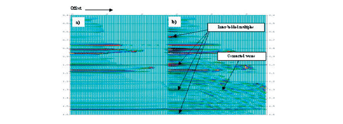
Figure 2 shows the cmp gathers generated by Zoeppritz modeling and finite difference method, respectively. It can be seen that Zoeppritz modeling gives clean primary reflections (Figure 2a). In the gather of elastic modeling, inter-bedded multiples and converted wave energy can be observed (Figure 2b). This is helpful to determine an appropriate data processing strategy to attenuate the noise and preserve the primary reflections. In elastic modeling, a specific event such as converted wave or multiple may be isolated through smoothing out a segment of the logs corresponding to a specific layer. Acoustic modeling may also be incorporated with elastic modeling to identify converted wave energy.
A synthetic cmp gather can be tied to a recorded seismic cmp gather at a well location to validate seismic response of known reservoir conditions. The reservoir conditions can be altered and the corresponding synthetic gathers can be calculated to examine the predicted seismic responses. The often-varied parameters for reservoir conditions are: thickness, porosity, water saturation, fluid type, and lithology. Contrast between lithological units is also of interest as it influences AVO responses as well. Further, frequency bandwidth and seismic wavelet are other parameters to be tested. NMO stretching and offset-dependent tuning may also be of interest. A variety of AVO attributes can be calculated from the synthetic modeled gathers. The most commonly used attributes are angle stacks, P- and S-impedance reflectivities, fluid factor, and gradient. Cross-plots of these attributes can be analyzed for meaningful relationships. Random and coherent noise can be added to study their effects on AVO attribute inversion.
When frequency or wavelet at reservoir level is given, correct rock physical property input becomes essential in single cmp gather modeling. Complete P- and S-wave velocity and density log curves from surface are the basic input. The procedure for obtaining correct rock properties for input involves log data QC, log data corrections, and rock physical property prediction. Quick results may be produced when dipole sonics are available. Before to do so, corrections on log data may require either for producing missing log segments or editing log curves. Tying to recorded seismic is an important QC step. The modeling result may help in identifying whether amplitudes have been properly recovered in data processing. The correct input model, especially in those areas without dipole sonics, requires information from geology, petrophysics, and even engineering.
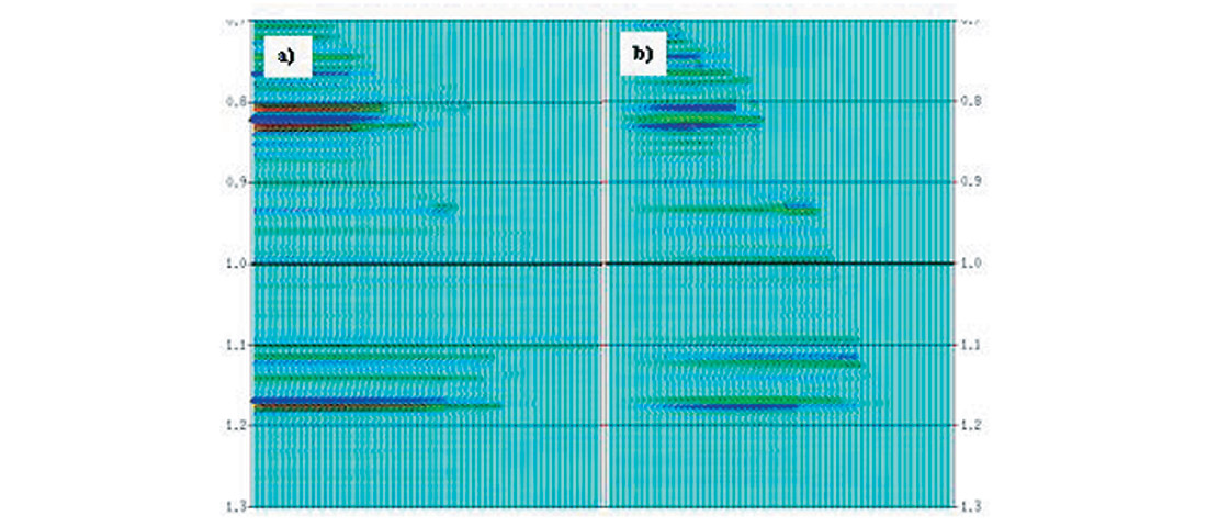
Converted wave modeling aims on the analysis for multicomponent seismic data that contains amplitude variation with offset information for both compressional and converted waves. The separated P-wave data (P-P) and converted wave data (P-S) can be used to perform P-wave AVO analysis and converted wave AVO analysis. The P-P data can incorporated with P-S data in AVO reflectivity inversion. Its advantages were summarized by Larson (1999), which includes: better signal-to-noise ratio due to larger amount of data; better S-reflectivity or S-impedance estimates due to that converted wave more depends on shear impedance contrast; and better elastic parameter estimates when P-P contrasts are weak or P-P data has low signal-to noise ratio. In addition, density information can be determined by using converted wave data (e.g., Jin et al., 1999). This may be typically useful for the areas where the density contrasts are considered better than P-impedance and S-impedance contrasts such as oil sand plays in the WCSB (Dumitresue et al., 2003). Figure 3 shows an example of AVO modeling using P-P and P-S Zoeppritz equations with ray tracing, where the travel time of converted wave gather is corrected to P-wave travel time.
3. Two-dimensional stratigraphic modeling
2-D stratigraphic modeling has the advantage of taking into account lateral variations in geology. The geological section to be modeled may come from seismic interpretation or can be constructed using well logs as control points. The lateral variation can be structure, reservoir thickness, porosity, lithology, fluid type, or fluid saturation. Based on the geological model of the subsurface rock properties, cmp gathers are calculated and then processed as a 2-D line.
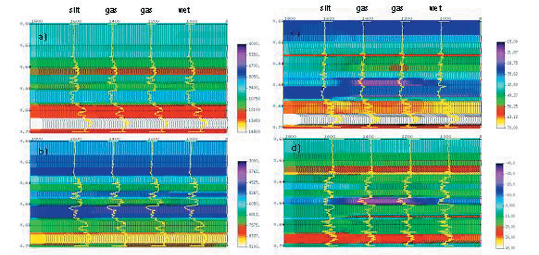
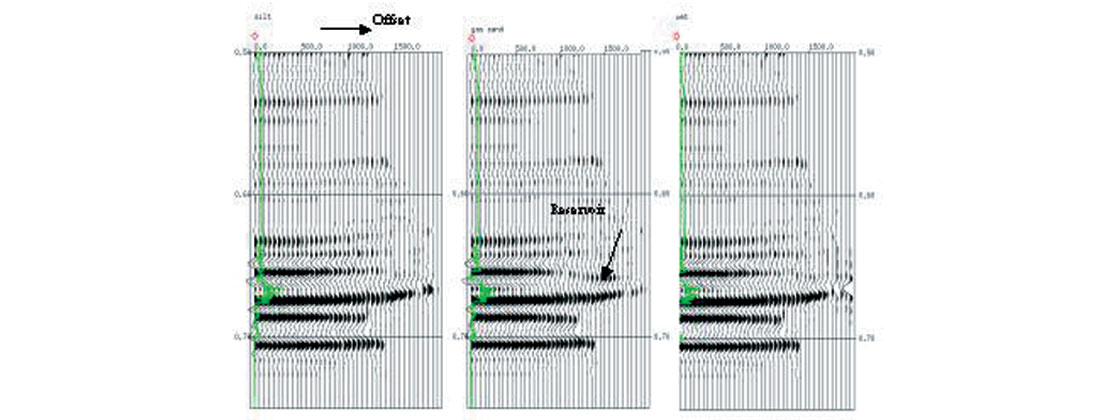
An example for a gas play with well control at four locations is shown in Figure 4 (Li et al., 2000). In this example, the target zone changes from silt sand, gas sand to brine-saturated sand. In total, 100 cmp gathers were generated. P- and S-reflectivity were extracted using Fatti’s equation and then inverted into P- and S-impedance sections. The lr and mr sections were calculated. For this case, we can see the difference in sensitivities of the inverted elastic rock properties in response to the gas: P- and S-impedances are unable to delineate the reservoir but λρ and λρ-μρ do. The cmp gathers at silt, gas sand, and wet well locations are shown in Figure 5. Class I AVO anomaly can be seen in the gather corresponding to the gas well.
4. Two-dimensional elastic wave equation modeling
Recently, there is renewed interest in 2-D and 3-D elastic modeling for AVO analysis in structurally complex areas. This is because seismic imaging alone does not describe a reservoir completely. Elastic modeling will help to solve some specific issues of AVO analysis in structurally complex areas. This includes correctly positioning the signals and the amplitudes, and determining the angles of reflection at a common image or reflection point. In comparison to ray tracing method, elastic modeling generates the most realistic synthetic data.
Conducting 2-D and 3-D full wave elastic modeling by using finite–difference method takes significant time. Recent advances in computing power have made single shot gather modeling trivial and 2-D modeling practical. Current major players in 2-D and 3-D elastic modeling include Los Alamos National Lab, Lawrence Livermore National Lab, University of Houston, and Stanford University. One recent accomplishment is converting the Marmousi model to an elastic version and generating shot gathers using full wave elastic modeling (Martin et al., 2002).
While 2-D stratigraphic modeling does not take the complete wave-field and structure effect into account, 2-D elastic wave equation modeling does. Another difference is that 2-D elastic wave equation modeling generates shot gathers instead of cmp gathers. The synthetic data needs to be treated as recorded data and taken through a processing sequence. In 2-D elastic modeling, field acquisition parameters can be used and 3- component data can be generated.
To demonstrate explicitly all the waveforms from elastic modeling and to make a comparison between acoustic and elastic modeling, a layered geological model is studied (Li et al., 2003). The P-wave velocity model was initially used by Kelly et al. (1982) to demonstrate acoustic wave equation modeling in seismic imaging and interpretation. Here, this model is converted into elastic that consists of P-wave velocity, S-wave velocity, and density models. The reservoir at the top of the anticline is modeled as gas-charged with Vp/Vs ratio equal to 1.5. The maximum dip of the layers is about 20 degrees. Figure 6b shows the snapshots from both acoustic and elastic modeling at a shot location on the right wing of the anticline. The waves can be identified include reflected compressional wave (PP) and converted S-wave (PS). The shot gathers from acoustic modeling and elastic modeling at the same location are shown in Figure 6c. It can be seen that, except for the converted waves, the amplitudes of the same events are different as well. This can be observed at the events of PP1, PP2, and PP3. It implies that elastic modeling data is required for true amplitude migration. The pre-stack time migrated and depth migrated results for this example are shown in Figure 6d.
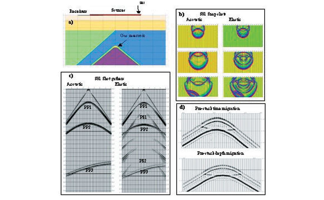
Figure 7 shows an example of elastic modeling using a model built by well logs. This model has dips as high as 45 degrees. A gas-charged reservoir is embedded in the top of the anticline, and another gas-charged reservoir is located at the fault. It is expected the effect of structure on amplitudes is significant for this type of structure. One hundred and ninety-one synthetic shot gathers were generated with a source interval of 50 m and maximum offset of 6000 m. The receiver station interval is 25 m. The shot gathers located at the top of the anticline, between the top of the anticline and the fault, and at the fault are shown in Figure 7b.
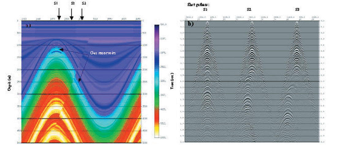
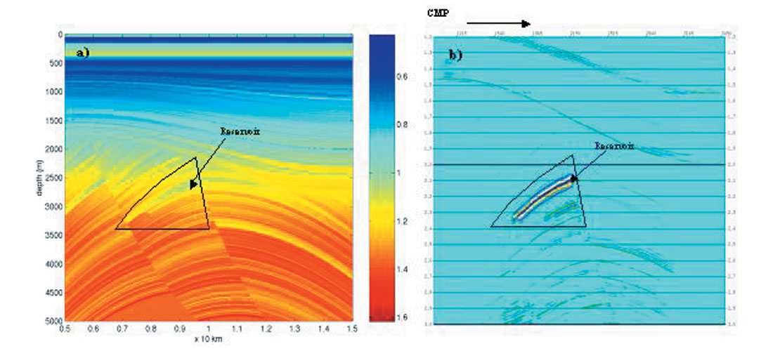
Figure 8 shows a pre-stack depth migration example using the data generated by elastic wave equation modeling. This study is typically for a structurally complex model in Mackenzie Delta, Canada (Xu, 2003). In processing the common image gathers after pre-stack depth migration were used. It can be seen that the reservoir is well characterized by the fluid factor stack, which would not typically be considered in interpretation of real data. Consequently, for a structure play, an a priori study may help to determine if AVO analysis is feasible or what kind of workflow can achieve optimal solution.
Conclusions
Single interface modeling, single cmp gather modeling, 2-D stratigraphic modeling, and 2-D elastic wave equation modeling have their pros and cons. The suitability of a method is determined by the objectives of a project. Regardless the methodologies, input model and calibration after the modeling are the key for successful application of AVO modeling in data processing and interpretation. It demonstrates that 2-D elastic modeling is an effective tool for studying AVO in structurally complex plays. It also demonstrates the fact that AVO modeling provides significant information in seismic data acquisition, processing and interpretation.

Acknowledgements
The authors would like to thank Core Laboratories Reservoir Technologies Division for supporting this work. The authors are also like to acknowledge the helps from and discussions with Bob Somerville, Huimin Guan, and Luiz Loures.


Join the Conversation
Interested in starting, or contributing to a conversation about an article or issue of the RECORDER? Join our CSEG LinkedIn Group.
Share This Article