Airborne electromagnetics (AEM) is easily one of the most popular geophysical methods used in mineral exploration around the world and is possibly second to only aeromagnetics-radiometrics as being the most widely deployed. AEM was initially developed after the Second World War to explore for mineral deposits (Fountain, 1998), and since then the search for conductive massive sulphide orebodies has remained one of its primary applications. Over this time period continuous advances in acquisition systems, calibration and data processing have extended its use from being simply a bump finding tool to being a sensitive and deeply penetrating geologic mapper; and its application has been extended to groundwater, engineering and hydrocarbon exploration (Smith, 2010). The large amount of money spent on AEM and the fierce competition for revenue between AEM manufacturers has led to continuous development of fixed-wing and particularly helicopter TDEM, systems on nearly a yearly basis throughout the past decades. This is manifested in the relatively large number of AEM systems and service providers found in the market.
In contrast, ground EM instrumentation, has remained unchanged over periods of years. Using the review article of Vallée et al. (2011) on metalliferous mining geophysics for 2000-2010 as a guide, nearly 6 of his 20 page journal article were dedicated to airborne EM alone, with only 3 ½ pages on all ground geophysical methods combined. Overall the competition in AEM systems has greatly benefitted the exploration industry through constant innovation and improvement, along with costs per km remaining relatively constant also, thereby maintaining the popularity of AEM surveys in mineral exploration.
Examination of Killeen’s (2014) and Vallée et al.’s (2011) reviews of AEM systems reveals an abundance of AEM systems, some new, some old, some renamed versions of older system, and some promising systems that are no longer available. Our paper will focus primarily on the state of the art commercially available AEM from the major service providers in Canada. Interested readers are referred to the reviews by Killeen (2014), Vallée et al. (2011), Allard (2007) and Sattel (2006) for more information on the evolution and variety of airborne EM systems currently available the world over.
AEM System Basics
As described by Swift (1987), electromagnetic methods include an initially confusing variety of techniques but each involves the same basic measurement of either an electric (E) or, characteristically for AEM, a magnetic (H) field using an “EM receiver”; and similarly the transmission of E- or, more usually for AEM, H-field energy using an “EM transmitter”. Figure 1a presents a schematic of a helicopter EM system, showing the induced (primary) and measured (primary + secondary) magnetic fields. Airborne EM systems have been typically classified according to the waveform of the transmitter source and how they are measured, referred to as either “frequency domain” (FEM) or “time-domain” (TEM). Airborne EM systems can also be classified according to how the EM fields are transmitted, either “active” (controlled) source, where both the transmitter and receivers are part of the instrumentation and would include all time-domain and frequency-domain systems (Swift, 1987); or “passive” (planewave) source, where only the receiver is part of the instrument and the EM field is created elsewhere, which would include natural field and VLF EM systems (Swift, 1987); as well as semi-airborne systems, typically involving transmitters on the ground, both loop (inductive) and grounded-dipole (galvanic) sources, and receivers in the air (ref. Fountain, 2008). Finally, AEM systems have also been classified according to fixed-wing (FTEM & FFEM) or helicopter (HTEM & HFEM) platforms, however this is semantic since all AEM systems discussed previously are capable of being flown aboard either fixed-wing aircraft or helicopter systems (Fountain, 2008), with the only distinctions being performance and payload.

As shown in Figure 1a, the EM measurement involves both a primary EM field related to the transmitter and a secondary EM field that relates back to the geology. In terms of methods, time-domain and frequency domain EM methods differ in how they remove the effect of the primary field (Swift, 1987). As a rule, frequency-domain EM systems induce sinusoidal fields at various frequencies and separate the secondary fields from the primary by subtracting the difference between the measured and predicted fields, with FEM data expressed as “In-phase” (IP) and “Out-of-phase” (or Quadrature=QD) components (see Fig. 1a). The bedrock conductivity is derived by comparing the IP and QD responses at various frequencies, as shown in Figure 2a. Whereas, typically, TEM systems only measure the secondary EM field decay during the “Off-time” (Fig. 1c), hence in the absence of the primary field, though most measure at least some On-time data also. TEM measurements consist of samples of the EM field that decays with time (Fig. 1c) and the bedrock conductivity-depth profile is derived by the field amplitudes and also how quickly the fields decay, as shown in Figure 2b. Passive AEM systems instead use field ratios or ground base-station receivers to remove the effect of the primary fields that are time-varying and generally horizontal from secondary fields that are largely vertical (ref. Labson et al., 1985; McNeil and Labson, 1991). Their data are expressed in units identical to those used in FEM systems (IP and QD). In all three methods, the FEM, TEM and passive EM, receivers measure at least 2-3 field components (Z=vertical axis, X=in-line horizontal, and sometimes also Y=cross-line horizontal). EM modeling and inversion are routinely used to resolve earth’s conductivity/ resistivity from these types of EM measurements.
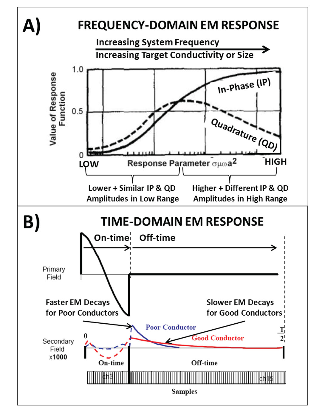
In terms of relative performance, it is generally acknowledged that time-domain EM systems are able to outperform frequency domain systems for mineral exploration (Nabighian and Macnae, 2005; Allard, 2007). However in other applications, FEM and passive EM can be competitive. As shown in Figure 2a, EM theory reveals that increasing the frequency range increases the range of resistivities that can be resolved. Hence because FEM systems are broadbanded, nearly spanning 3-decades of frequencies (~300 Hz to ~150k Hz), and measure both In-phase and Quadrature, their sensitivity can span nearly 5 orders of magnitude in resistivity (0.1-50,000 ohm-m) (Hodges, 2013). In comparison, modern TEM systems have an expanded frequency bandwidth (~25Hz to >100k Hz) but measure only the off-time EM response. As a result their sensitivity is limited to a maximum span of ~4 decades of resistivity, as well as generally being less sensitive in high resistivity range, as compared to FEM (Macnae, 2007; Macnae, 2015*). However TEM systems operate in a lower frequency range that allows them to distinguish higher conductivities (up to 1000 S/m) relative to FEM (Macnae, 2010; Hodges, 2013). Combining this shift in frequency content with EM skin depths, it can be seen that the higher frequency content in FEM signals gives then a reduced depth of penetration compared to TEM systems (Hodges, 2013). On the other hand, because frequency-domain measurements involve the detection of relatively small secondary fields in the presence of large primary fields, precise measurements require instruments that tend to be rigid and smaller size, as well as less powerful, which further limits their depth of investigation. For example, the transmitter dipole-moment (i.e., total loop area x loop current=NIA), a measure of system power, for FEM systems is typically less than 300 NIA, whereas TEM systems are typically in the 0.1-2 million NIA range (Macnae, 2007), thus 100-1000x more powerful. Thus ATEM systems tend to feature larger and more powerful transmitters, which are able to penetrate more deeply than AFEM systems, due to higher signal to noise ratio (Allard, 2007).
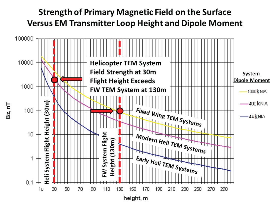
Figure 3 compares primary magnetic field strengths for FTEM and HTEM systems based on flight-height and transmitter dipole-moment, which is a measure of system power. It demonstrates how helicopter towed-bird systems, by virtue of lower receiver flight-heights, are capable of larger primary fields, hence increased penetration, than larger, more powerful fixed-wing systems. This explains the popularity of HTEM in exploration circles. That said, passive AEM systems such as AFMAG that operate at low frequencies (~25-1000 Hz) have the largest relative depth of penetration of all, in the order of km (Lo et al., 2009), since they are unencumbered with generating primary fields from transmitters whose strength falls off as 1/distance squared, as shown in Figure 3, such as those from active-source TEM and FEM systems. However the operational frequency bandwidth for all AEM systems is limited at the high frequency end by dielectric permittivity effects. These appear at 100 kHz for frequency domain systems and for earliest time data (<1μs) for time-domain systems (Yin and Hodges, 2005; Macnae, 2007; Hodges and Chen, 2014c). AEM systems are currently limited to 10-15 Hz at the low frequency end by the effects of wind-shear and external (tow-cable, aircraft, etc.) sensor noise (Macnae, 2007).
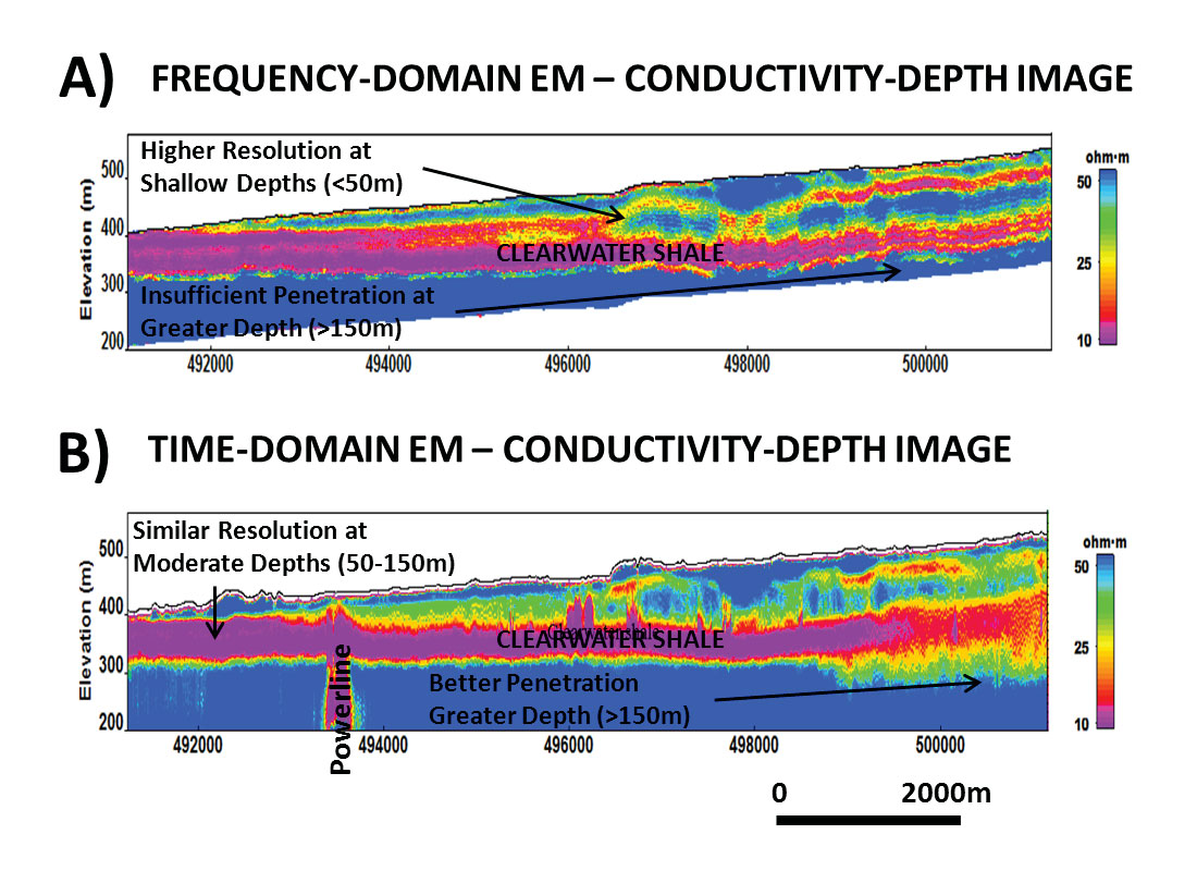
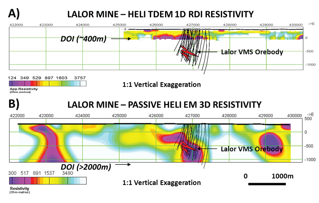
Generally speaking, airborne TEM should be considered in cases of thick, conductive cover, for mapping deeply buried (>150m) geology, and for discriminating more highly conductive (>10 S/m) targets (Macnae and Nabighian, 2005; Macnae, 2007). Airborne FEM should be considered when targets are poorly conductive, when host rocks are resistive (>10000 ohm-m) and when near-surface (<50m) resolution is critical, such as in hydrogeology, engineering and gold or kimberlite exploration (Holladay and Lo, 1997; Hodges, 2013). Passive AEM should be considered when mapping large mineralized systems and when large depth of investigation (>500m) are required (Legault et al, 2014). Figure 4 presents a comparison between conductivity-depth images obtained from helicopter frequency-domain and time-domain EM system surveys over Clearwater shales in the Fort MacMurray, Alberta, region that illustrate some of the main differences between these two types of EM survey techniques. Figure 5 presents a similar comparison between helicopter time-domain and passive EM systems over the deeply buried (600-1200m) Lalor zinc-copper-gold deposit in northern Manitoba.
AEM System Development
Of the many developments in AEM from 2000-2015 , none have been more important than the advent of helicopter time-domain EM (HTEM) systems (Vallée et al., 2011; Allard, 2007; Fountain et al., 2005; Fountain, 2008). Mining geophysics remains the main focus of airborne EM developments based on revenue, compared to groundwater, engineering and hydrocarbons. However it is no longer the case that airborne EM manufacturers are specializing in different markets – in fact, more and more systems are being designed to service as many markets as possible. For example, ten years ago SkyTEM (Sørensen and Auken, 2004) would have designed its single AEM system specifically for hydrogeology, Geotech’s VTEM (Witherly et al., 2004) for mineral exploration and only Fugro (now CGG) produced systems designed for both types of applications (Smith and Fountain, 2005; Fountain et al., 2004). Today manufacturers have learnt from each other and adapted their own systems for the widest variety of applications possible, from mineral exploration to groundwater to engineering.
As an example, the SkyTEM MULTIMOMENT system that is known for its combination of short pulse/long pulse for improved groundwater imaging now showcases a >1M dipole moment system and gives better late-time data quality for deeper penetration that specifically targets mining exploration (Sørensen et al., 2013). The Geotech VTEM system, whose earlier focus on late-channel data quality for deep mineral exploration proved widely successful in the mining market, has since shown that, by implementing a single pulse, full-waveform capability to improve its near-surface imaging for groundwater, this has also helped in mining environments (Prikhodko et al., 2013; Bagrianski et al., 2014). CGG/Fugro developed a MULTIPULSE technology (Chen et al., 2013) to improve its near-surface imaging for groundwater, and now implements MULTIPULSE on all its fixed-wing and helicopter AEM systems to improve their shallow resolution capability (see CGG website). Thus consumers have more choices in high-end AEM systems from more manufacturers and providers than ever before.
In sharp contrast, as predicted by Allard (2007), airborne frequency domain EM (AFEM) system development has for all practical purposes stalled over the last decade, with no significantly new AFEM systems having been brought on-line in this less-competitive environment (Fountain., 2008). Of the 22 operational FEM systems described by Holladay and Lo (1997), there remain perhaps only 4-5 at present. CGG continues to fly RESOLVE and DIGHEM and Geotech with the IMPULSE system primarily for shallow exploration for diamonds, groundwater and engineering applications. And Sander and Geotechnologies fly their fixed-wing FEM systems for mineral reconnaissance applications. Yet, for most mining exploration, the preference by industry clients for increased depths of investigation has seen helicopter FEM systems muscled out of the market by low cost, light-weight time-domain heli-EM systems that satisfy this requirement. In spite of successful design testing of GEMINI FEM system concept (Smiarowski and Macnae, 2007; Witherly, 2009) for more deeply buried, high conductance nickel targeting, it failed to see further application for mineral exploration. Of the 70 papers presented at AEM 2013, only two (Hodges, 2013; Vovenko et al., 2013) dealt with frequency domain systems. Interested readers are referred to reviews by Vallée et al. (2011) and Thomson et al. (2007) on frequency domain EM systems.
On the other side, ground EM systems are now being competed against by semi-airborne AEM systems, such as heli-SAM (sub-audio magnetics) using ground EM loops and airborne receiver combination that are now able to descend to lower frequencies (<15Hz) and use equally higher power transmitters to provide equivalent penetration (>1.5km) for higher conductance targets at depths similar to ground EM systems (ref. Parker et al., 2014). ZTEM passive AEM is also being used in combination with ground MT through joint-2D-3D inversions for improved resolution and depth-characterization within the upper 1km (Legault and Wannamaker, 2014). The new software development for continued high quality AEM system data has now made it possible to extract IP parameters for mapping chargeability from TDEM decay data (Kwan et al., 2015; Hodges and Chen, 2014b). Current trends indicate that airborne equipment manufacturers will do more to compete with ground EM systems in the future.
Time Domain EM Systems
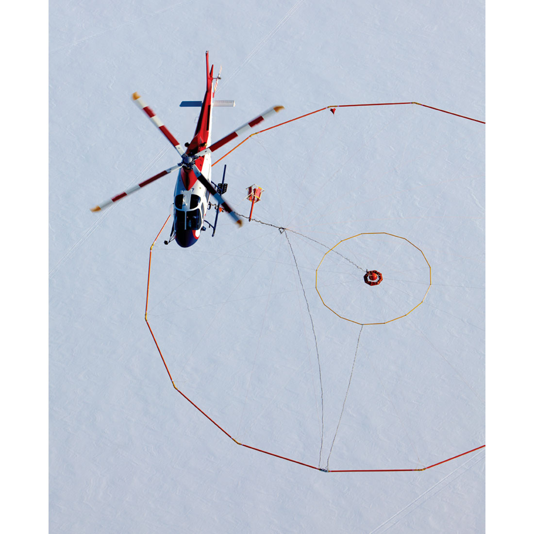
In its 30 year history, Geotech Ltd, of Aurora, Canada, has grown from frequency-domain EM instrument manufacturer to likely the largest helicopter time-domain EM service provider in the world. The VTEM system, which is one of the most widely used helicopter EM platform in mineral exploration, is recognized for its high signal to noise and large dipole moment, providing both high data quality and large depths-of-investigation. It operates three variants of its successful VTEM (versatile time-domain electromagnetic) 25/30Hz systems, including: the VTEM lightweight 18m diameter system and the VTEMSPEEDY design variant (Killeen, 2015) with reinforced airframe for faster airspeed, the VTEMPLUS 26m dia. system with 450k NIA dipole-moment and the high power VTEMMAX 35m dia. system with 1.5M NIA dipole-moment (Fig. 6). VTEMMAX is the first AEM system to detect the deeply buried (>350m) Caber North VMS deposit in northern Quebec (Killeen, 2013). The newest system VTEMXTREM with >2M NIA dipole-moment uses a larger area loop and more powerful transmitter for higher signal to noise than previous VTEM systems (Killeen, 2015). Geotech also continues to operate the AEROTEM IV system (Balch et al., 2003) with its rigid 12m transmitter platform and on- and off-time measurement capability from a triangular 50% duty cycle waveform at 25/30 and 75/90Hz. In addition to improving its depth of investigation using increased dipole-moments, the VTEMPLUS system now boast improved aeromagnetics via a horizontal magnetic- gradiometer that is unique among current HTDEM systems (Killeen, 2012). As well, they have adopted the Full-waveform adaptation for the VTEM system (Prikhodko et al, 2013) that uses continuous time-series recording, pre-survey calibration and signal deconvolution to significantly improve their early-time data and near surface resolution, while maintaining its extended depth of investigation. This adaptation can be used on most of its VTEM systems at no additional cost.
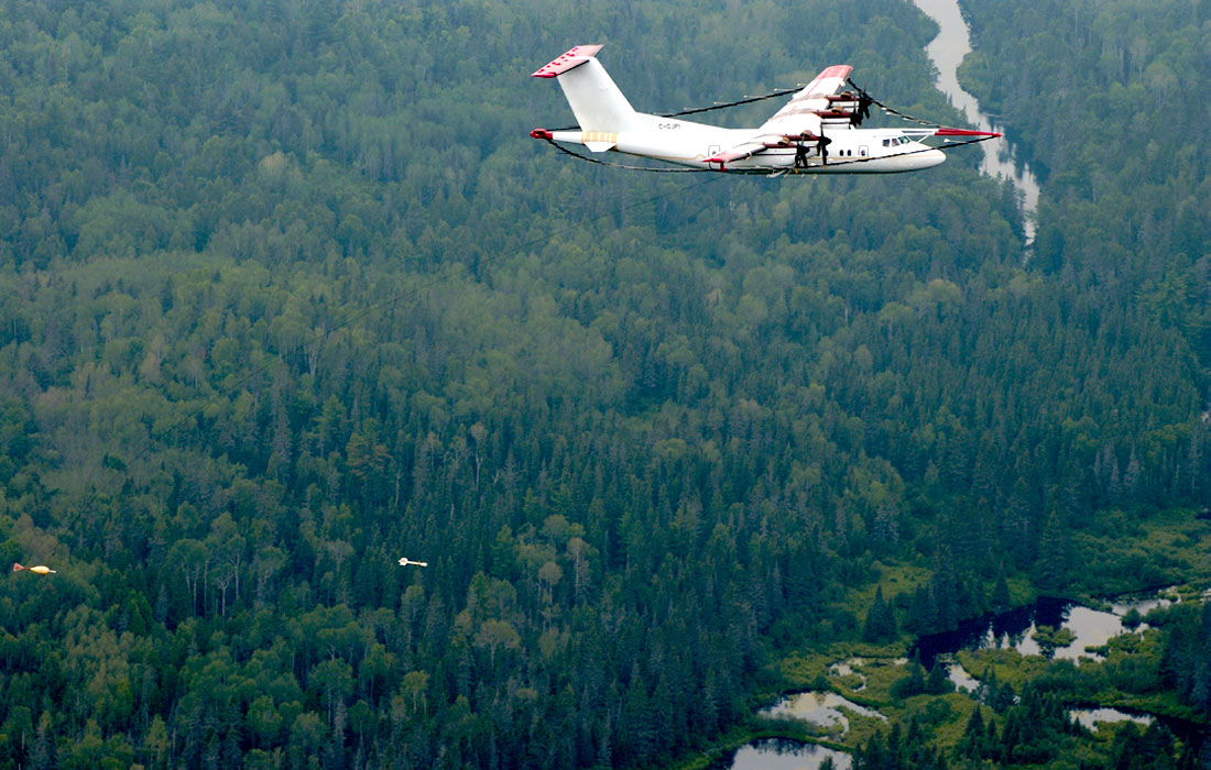
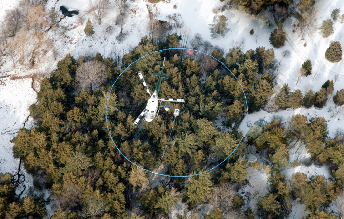
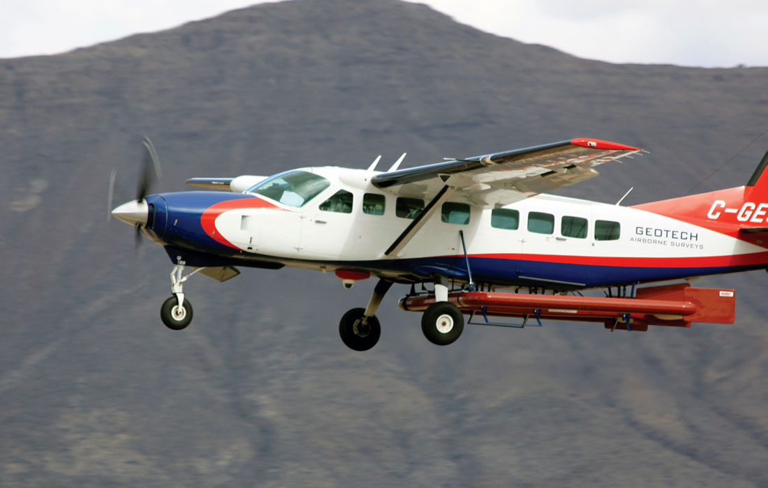
CGG of Paris France, one of the largest geoscience companies in the world, is also a leading provider of state-of-the art airborne geophysical surveys, after its acquisition in 2013 of Fugro Geoscience Division. CGG is one of the few providers of both fixed-wing and helicopter EM systems in the world. Its fixed-wing systems include the successful MEGATEM large dipole moment (2M NIA) TDEM system (Fig. 7) that operates at 30 and 90Hz from a transmitter loop mounted on a Dash-7 aircraft and towed 3-component EM bird (Smith and Fountain., 2005); the GEOTEM system is a similar but slightly less powerful (1M NIA) fixed-wing TDEM platform that uses a smaller CASA212 aircraft and been operational since the 1980’s; the lightweight GENESIS TDEM introduced in 2007 that operates on the single-engine Cessna Grand Caravan; and finally the TEMPEST system, designed for groundwater and mapping work, that is broad-banded and uses a square-wave waveform with the same three-component receiver sensor used by the GEOTEM system. Included in the CGG fixed-wing TDEM systems is the multi-parameter GRYPHON (Killeen, 2014) that combines TDEM, magnetics, gravity-gradiometry, laser-scanning and radiometrics on the same airframe. The HELITEM time-domain EM system (Fig. 8), currently the highest-power helicopter TDEM system in operation, with a 2M NIA dipole-moment (Killeen, 2011), was shown to be the first ATEM system to detect the deeply buried Lalor VMS deposit at >550m depths (Hodges and Chen, 2014). In 2010 CGG improved upon HELITEM by moving its 3-component receiver from a free-hovering bird used by its fixed wing cousins MEGATEM-GEOTEM-GENESIS- TEMPEST to being fixed at the yoke above its transmitter loop, moving it closer to the ground level for improved sensitivity. Moreover, a major step in 2014 was the conversion of all its AEM systems from single-sine wave pulse to MULTIPULSE technology for improved near-surface characterization (ref. CGG website).
The SkyTEM (Fig. 9), developed in 2004 in Denmark by SkyTEM Aps in close collaboration with Arhuus University (Sørensen and Auken, 2004), was originally a single design intended primarily for mapping hydrogeology. The SkyTEM introduced a breakthrough feature: being able to excite the earth at multiple base frequencies (e.g., at 25 Hz and 225 Hz). This was achieved by having two separate transmitters, one of which transmits a relatively small signal at a base frequency of 222 Hz for a fraction of a second and then switches off, and the other of which transmits at 25 Hz for about a second (Vallée et al., 2011). This allows SkyTEM systems to continuously excite and measure the earth response over a much broader frequency bandwidth than competitive systems. This technology has since evolved into the MULTIMOMENT technology with high and low moments on the same waveform (Effersø, 2014). SkyTEM currently features as many as five different systems (see SkyTEM website), including: 1) SkyTEM301, a near-surface focused system applying a single turn transmitter loop; 2) SkyTEM304/312 which are medium duty systems with either four or twelve turn transmitter loops; 3) SkyTEM-FAST systems can be operated up to 80 knots production speed; 4)SkyTEM508 is a heavier system applying an eight turn transmitter loop; and 5) SkyTEM 516, which has the largest dipole-moment (>1M NIA) and deepest penetration of all SkyTEM systems. It was able to successfully detect the deeply buried Caber North deposit (Effersø, 2014). All SkyTEM3XX systems are mounted on a rigid 349 m2 carrier frame and can be configured for either regular or fast operation; whereas SkyTEM500 series systems are mounted on a rigid 548 m2 carrier frame (see SkyTEM website). The strength of the SkyTEM system is the shortest transmitter turnoff, earliest decay sampling and fully calibrated instrumentation, providing the high quality shallow near surface characterization, while improving its depth of investigation using increased dipole-moment transmitters.
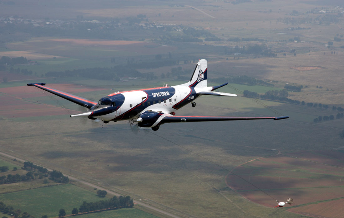
SpectemAir Ltd., of Johannesburg, South Africa, are operators of the innovative fixed wing SPECTREM2000 time-domain EM system (Fig. 10), previously proprietary to the DeBeers and Anglo American mining companies prior to 2003 (see Spectrem website). It is characterized by full on-time measurements of the dB/dt fields using a 100% duty cycle square current waveform that results in a step-response signal at the receiver (Leggatt et al., 2000; Leggatt, 2013). SpectremAir remains the only competitor to CGG for commercial fixed-wing AEM time-domain EM systems. Spectrem2000 is mounted on a Basler-modified Douglas DC3 Dakota aircraft. The SPECTREM2000 system is distinguished by being a wideband system, with highest available transmitter dipole-moment of AEM systems, whose signal is deconvolved to a B Field step response for detecting widest range of high and low conductance targets.
Other Time Domain and Frequency Domain EM Systems
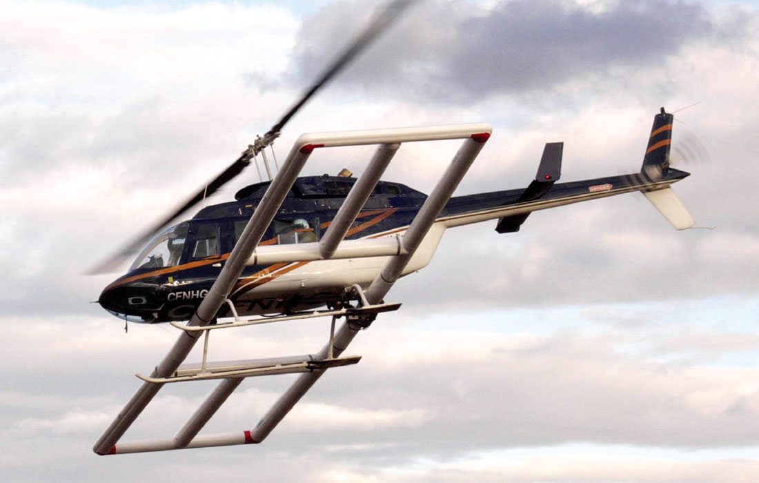
Australian-based helicopter time-domain EM systems such as the XTEM by GPX Surveys (Vallée et al., 2011), S-TEM by Thomson Aviation (Killeen, 2014) and Geosolutions’ RepTEM (Sattel, 2006) all operate relatively low-dipole moment, lightweight HTDEM systems that compete in the market. Similarly Quebec-based companies like GPR with their GPR-TEM, EON Geosciences with E-THEM and Markham Ontario’s Pico-Envirotec with P-THEM (Killeen, 2014) have all implemented variants of the THEM system designed by Kremer (Thomson et al., 2007) and described by Bodger et al. (2005), Allard (2007), and Vallée et al. (2011). Quebec’s Novatem operates a rigid helicopter TDEM system with its receiving loops located in the zero field, close to the transmitter in a central loop configuration (see Novatem website). BC’s Precision GeoSurveys (see Precision Geosurveys website) operates the 1TEM helicopter TDEM system that is based on GeoSolutions REPTEM; and AirTEM has its own advanced HTDEM system that features a transmitter-receiver bird that also carries a high-sensitivity magnetometer (see AirTEM website). Geotechnologies, based in New Jersey (see Geotechnologies website), operates its EQUATOR helicopter TDEM (Volkovitski and Karshakov, 2013) and EM-4H fixedwing quadrature FEM systems (Vovenko et al., 2013; Killeen, 2014). Battelle Research Institute, at the US Department of Energy’s Oak Ridge National Laboratory in Tennessee, have developed their innovative, boom-mounted, 225Hz TEM-8 helicopter time-domain EM system (Fig. 11) that flies at ~2 m heights for unexploded ordnance (UXO) detection (Doll et al., 2010). Sander Geophysics, of Ottawa, Ontario, operates its SGFEM frequency-domain EM system (Fig. 12), the only other fixed-wing FEM system in operation worldwide that was originally was developed by the Finnish GTK and used by British BGS (Vallée et al., 2011). Measuring secondary EM fields at 912-24.5k Hz from 4 coaxial wing-tip Rx-Tx pairs, SGFEM system also acquires mag-gradiometric, laser-altimeter, radiometric and gravity (AirGrav) data from the same platform (Killeen, 2014).
CGG manufactures and operates the RESOLVE and DIGHEM helicopter frequency domain EM (HFEM) systems (see CGG website). RESOLVE (Fig. 13) is an FEM system that has the transmitter and receiver fitted in an 8m long cylindrical towed bird and operates at 1-6 frequencies (400-140k Hz) using coplanar and co-axial receivers. RESOLVE is primarily used for shallow-penetrating (<100m) groundwater and engineering applications. CGG’s DIGHEM frequency domain EM system is a similar towed-bird FEM system that employs 2-5 pairs of coaxial and coplanar transmitting and receiving coils at 900-56000 Hz. DIGHEM is mainly used for mineral exploration application up to 150m of penetration (see CGG website). Geotech Ltd. operates the IMPULSE HFEM system previously manufactured by Aeroquest. IMPULSE is a towed-bird helicopter system used primarily in shallow mineral exploration that has coplanar and coaxial Tx-Rx pairs at 330 Hz-90k Hz, along with an integrated magnetic gradiometer, which has a maximum depth of investigation of approximately 100m (see Geotech website).
Passive, Semi-passive and Semi-airborne EM Systems
Passive and semi –passive electromagnetic systems are those which do not have an active controlled source transmitter on the aircraft, as with time-domain and frequency domain EM systems discussed earlier. This can be achieved in 2 ways using: (1) naturally occurring EM fields, in the case of passive EM systems; and (2) distant uncontrolled/ remotely operated EM sources such as communications and powerline grids, for semi-passive EM systems. Semi-airborne EM systems use either a ground based EM transmitter in conjunction with airborne EM receivers, or vice-versa.
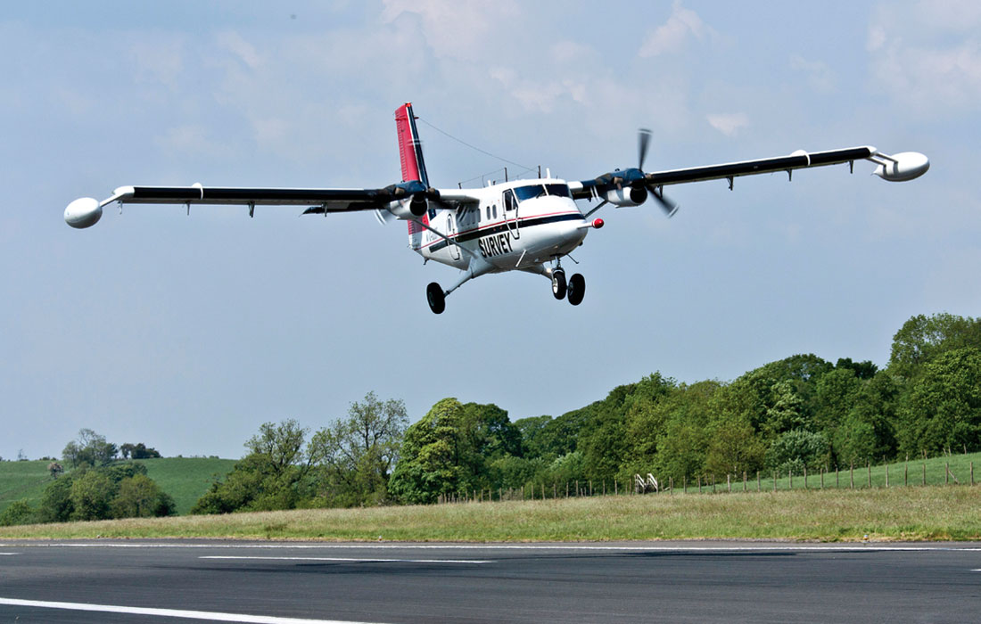
Geotech Ltd., in addition to being a leading time-domain helicopter EM manufacturer and survey provider, also leads in the non-time domain system market, having developed the ZTEM (Z-axis Tipper Electromagnetic; Lo and Zang, 2008) and AirMT (Airborne Magnetic Tensor; Kaminski et al., 2010) airborne AFMAG (Ward, 1959; Labson et al., 1985) passive EM systems that use naturally occurring EM fields generated by local and worldwide thunderstorm activity as their primary EM fields – thus dispensing with an on-board transmitter. ZTEM measures the z-component (vertical component) of the natural fields, using an airborne receiver, and it also measures the horizontal components at a remote ground station. Rather than being assumed to be the same at the helicopter, the difference in the horizontal EM components are accounted for in the interpretation, by 2D and 3D inversion methods (Holtham and Oldenburg, 2008). In addition to benefitting from a large, otherwise untapped primary EM field source, the natural fields produced by sferics are uniform, horizontal and planar as well as being broad-banded thus able to achieve penetration depths unequaled by controlled-source EM platforms – in the order of km’s. Used primarily for porphyry copper, unconformity uranium and epithermal gold exploration, to date it has flown over 350,000 line-km and remains the only airborne AFMAG technology to be flown commercially in over 30 years (Legault, 2012). ZTEM was the first AEM system to detect the deeply buried Lalor VMS deposit (Legault et al., 2014). A new fixed-wing implementation of the ZTEM system, FW ZTEM (Fig. 14) uses a redesigned aerodynamic receiver with integrated total field magnetometers and is retractable using a hoist and cradle system (Legault, 2012). Operational since early 2011, FW ZTEM saw its first international commercial survey application in Namibia for deep penetrating regional geological mapping in summer 2014 (Killeen, 2015).
VLF (very low frequency) electromagnetics (McNeil and Labson, 1991) have long been used as bolt-on EM instruments and flown routinely aboard aeromagnetic system platforms. VLF-EM is a semi-passive electromagnetic method that employs energy in the 3-30 kHz band, typically broadcast by naval transmitters for submarine navigation. Under good conditions, VLF-EM can be sensitive to conductivity variation to 100 metre depths. The venerable Totem IIa, manufactured by RMS Instruments, of Mississauga, Canada, has been in continuous production, virtually unchanged since the 1970’s (see RMS Instruments website). Terraquest Ltd., of Markham, Canada has developed the new XDS-VLF passive EM system. Unlike standard VLF receivers, XDS VLF can acquire data in the standard mode, tuned to a particular VLF transmitter, as well as operating in a broadband mode spanning from 12 to 35 kHz, measuring signals from orthogonal transmitter-sources simultaneously (see Terraquest website). This increases the reliability of the XDS measurement in comparison with standard VLF. XDF VLF is purported to have defined a gold-bearing feature, undetected by passive and active AEM systems in the Ring of Fire of Ontario, Canada (Greenough and Palmer, 2010).
The tensor VLF technique and fixed-wing system developed at Uppsala University and deployed by the Geological Survey of Sweden represents a step up in airborne VLF technology relative to most existing North American systems. Unlike conventional VLF systems, which are analog, tensor VLF adopts full time-series FFT-based processing similar that used in ground tensor audio-magnetotelluric tipper methods and the ZTEM technique, but applied to VLF fields (Pedersen, 1998). To date, however, the tensor VLF AEM surveying has not been commercially available.
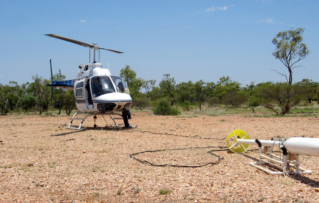
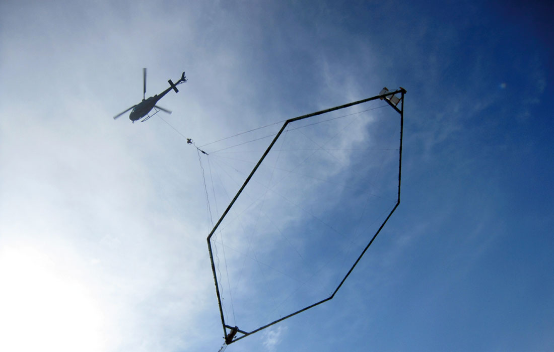
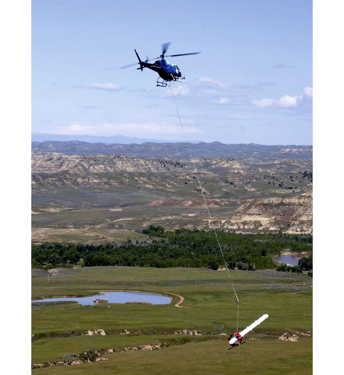
Semi-airborne systems that have been developed include the GREATEM system (Mogi et al., 2009; Verma, 2013). A new innovation, recently introduced in Canada by Discovery Geophysics, Vancouver, in collaboration with GAP Geophysics, of Brisbane, Australia, is the heli-SAM (Sub-Audio Magnetics) semi-airborne system (Fig. 15), that measures the EM signal from a grounded dipole or fixed loop using a cesium vapour magnetometer while is towed from a helicopter platform (Chubak et al., 2014; Parker et al., 2014). Originally designed to explore below the deep conductive overburden of Australia, SAM is distinguished by its capability to operate at low frequencies, 4-20Hz – easily below the current 15-25Hz threshold of current ATEM systems, allowing it to resolve highly conductive and deeply buried conductive orebodies below 1.5km depths. Such targets would formerly only attainable using more expensive ground TEM systems or using passive AEM. Recent heli-SAM examples from Canada include heavy oil sand delineation in northern Alberta (Chubak et al., 2014) and the Lalor VMS orebody in northern Manitoba (Parker et al, 2014).
Other AEM Development
One of the key AEM developments for EM sensor design concepts since 2000 was the indirect measurement of the B-field response for time-domain EM that is obtained by integrating the on- and off-time response of an induction coil (dB/dt) sensor (Vallée et al., 2011). First proposed by Smith and Annan (2000) it has been widely used by AEM system providers ever since. Advantages of B-field acquisition include suppression of overburden responses and enhancement of high conductance targets. Since then there has been the promise of a full induction measurement, either via SQUID (Vallée et al., 2011) or other B-field sensors, such as an airborne version of the ARMIT sensor (Macnae, 2012) – unfortunately neither of these have yet been successfully implemented on commercial airborne EM systems. The suppression of wind shear noise on these sensitive sensors using suspension systems as well as external noise are the likely causes (Macnae, 2007).
FFT (Fast-Fourier-transform) time-series processing of airborne EM data have been used for conversion of real waveform to an idealized waveform such as an impulse or a step. This is the procedure used in processing data from fixed wing time-domain EM systems such as the SPECTREM system (Leggatt et al., 2000) and the TEMPEST system (Lane et al., 2000). This concept was also proposed by Macnae and Baron-Hay (2010) to improve early-time data in helicopter AEM system. Full Waveform deconvolution since been implemented by Geotech (Prikhodko et al., 2013) and is now in routine use on most of its VTEM systems for improved early-time/near-surface characterization.
The effects of induced polarization in airborne time-domain EM data that were initially described by Smith and Klein (1998) and Boyco et al. (2001), and recently examined by Kratzer and Macnae (2012). The extraction of AIIP (airborne inductive induced polarization) now represents one of the more promising AEM derived parameters to be introduced via data post-processing (Kaminski and Viezzoli, 2015; Kwan and Prikhodko, 2015). A proof of concept using 3D inversion modeling of airborne TDEM data was demonstrated in Marchant et al. (2014) and Kang et al. (2014). With the subsequent work of Hodges and Chen (2014b) and Kwan et al. (2015), using fast 1D TDEM inversion that incorporates Cole-Cole chargeability parameters, future commercial implementation of airborne IP extraction and removal for time-domain EM surveys now seems possible.
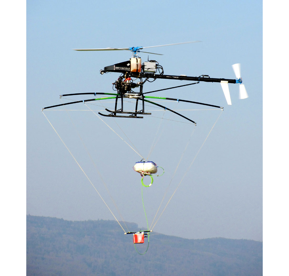
One of the newest areas of interest for airborne EM is in UAV (un-manned airborne vehicles) a.k.a. drone technology (Eröss et al., 2013). Drones for geophysical surveying were first investigated by Fugro Airborne (now CGG) who obtained a patent in 2005 for a UAV for acquiring aeromagnetic data (Keeler et al., 2005). The GEORANGER successfully acquired aeromagnetic data in 2005 (Killeen, 2006) but the UAV program was later abandoned (Samson et al., 2013). In 2011, Sander Geophysics collaborated with Carleton University, Ottawa, in the design and testing an UAV for aeromagnetic surveying, the GEOSURV II (Killeen, 2013). The Carleton UAV study is now in partnership with Stratus Aeronautics of Calgary (Samson, 2014). Recently, MGT (Mobile Geophysical Technologies), of Cologne, Germany, has integrated magnetic, infrared, radar, natural gamma ray and also radio-electromagnetic sensors on a UAV drone (Fig. 16). Radio EM is a passive AEM technique, similar to VLF, but in the 5k-250k Hz range (Stoll, 2015), requiring only a lightweight Hx-Hy-Hz sensor to be carried on board the UAV (see MGT website).
Conclusions and Future Directions
In the last five years, the continued dominance of helicopter time-domain EM systems remains one of the major developments in exploration geophysics. The major reasons for this have been cost effectiveness and design innovation over other competitive systems, airborne or ground. Further advances have been made in passive AEM for porphyry copper and epithermal gold exploration, with airborne inductive IP being on the verge of commercialization. More recently semi-airborne EM has been shown to possibly compete with ground EM for deep exploration of VMS deposits and delineation heavy oil sands. While it is difficult to predict where the future directions lie in the secretive and highly competitive world of AEM geophysics, there can be no doubt that in the current industry downturn, investment will continue in R&D research for improved instrumentation and innovation. Future directions will be dictated by current and future demands from mining industry and mineral resource clients.
Areas for improvement and innovation include lower frequency (<25Hz) AEM measurements, using higher quality airborne sensors advanced suspension systems and improved external noise reduction. Demand will continue for improved early-time data from ATEM system providers. This will certainly be accompanied by improvements in frequency-domain and passive EM systems, with increased bandwidth at low and high frequency bands. Progressively deeper investigation depths will be enabled by improved signal to noise from quieter and better calibrated EM systems. Continued increases in dipole-moment seem likely for bragging rights to the current gold standard. Improvements in hybrid frequency-and time-domain EM systems, either ground to air transmitters or air-to-ground systems seems logical for deep mining and hydrocarbon applications. Passive AEM from UAV systems appears promising, however the main impediment to drone geophysics remains FAA regulatory restrictions on commercial UAV operations. There is no doubt that airborne EM system designs will continue to lead mining, mineral, hydrogeological and engineering applications for geophysics into the future.

Acknowledgements
This paper has built upon the ideas and analyses put forth by Vallée et al. (2011) in their excellent review paper on advances of geophysics for metalliferous sulphides. The papers on airborne electromagnetic from the Fifth Decennial Conference on Mineral Exploration were also noteworthy sources for this paper, notably by Allard (2007), Macnae (2007) and Thomson et al. (2007). The yearly review articles by Killeen in The Northern Miner’s Exploration Trends & Developments (i.e., Killeen, 2014) track new advances on a year in/year out basis of both airborne and ground geophysical systems worldwide. We thank all the system providers for the photos of their systems. We also thank Martyn Unsworth for his helpful editorial suggestions for improving this paper.


Join the Conversation
Interested in starting, or contributing to a conversation about an article or issue of the RECORDER? Join our CSEG LinkedIn Group.
Share This Article