Compared to time migration, depth imaging should yield simpler structure, higher spatial and vertical resolution, and a more stable phase response. It is also the appropriate input for inversion and other attributes that estimate reservoir properties and mitigate risk. However, the interpreter must actively guide the depth-imaging process to ensure a reasonable, geologic result. This presentation reviews the planning and QC of depth imaging projects in a manner that establishes an appropriate dialogue between the interpreter and the processor.
Planning a depth-imaging project begins with the bidding. The company (or companies) selected must provide the level of technology suitable for the interpretive goals. As such, the dialogue should include:
- Defining deliverables in terms of interpretive goals
- Establishing a minimalist approach to initial time processing
- Choosing appropriate migration and tomography algorithm(s)
- Establishing the target (final) velocity resolution
- Defining a schedule for the tomographic updates
- Ensuring deliverables are compatible with 3rd-party software
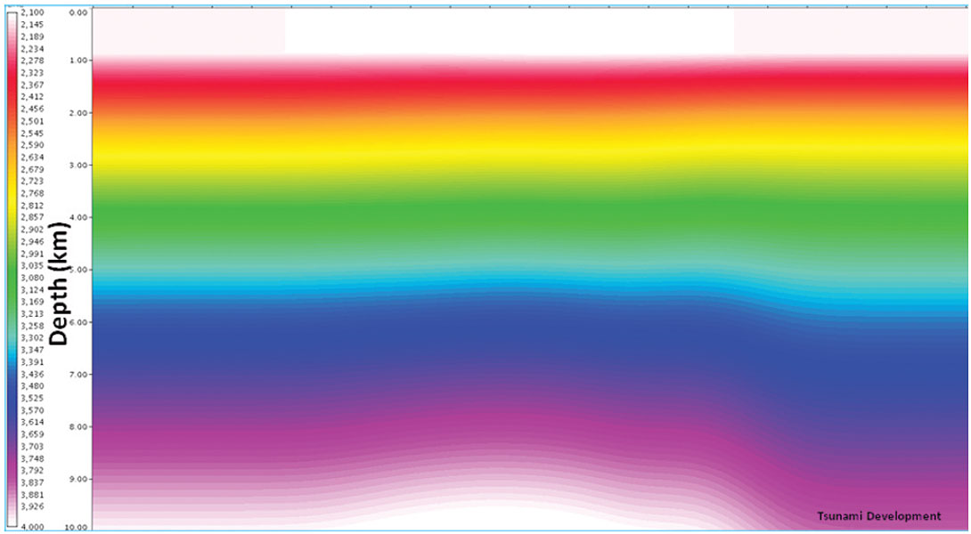
When beginning the imaging process, a critical step is the formation of the initial velocity model. Figure 1 is an example of an acceptable, smoothly-varying model. It is becoming popular to introduce shallow, refraction-based velocity solutions. In general, the addition of detail early in velocity-model formation must be approached cautiously.
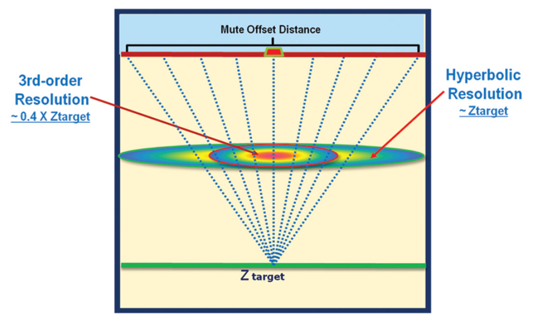
Depth imaging is an iterative procedure that seeks to add detail to the velocity model by means of tomographic refinement. Therefore, early in the planning of a project, it is important to establish realistic goals for the resolution we may expect from tomographic updates. Figure 2 illustrates an intuitive approach to establishing the target velocity resolution for an anomaly assumed to be halfway between the surface and the reflector. Basically, hyperbolic scanning of (offset = depth muted) gathers can only resolve an anomaly having a width equal to the depth of the reflector. A simple 3rd-order fit can resolve a narrower anomaly within the “ray” coverage of the gather. By establishing the target velocity resolution we may next establish a well-defined start and end of the tomographic-update process that avoids introduction of excessive velocity detail and potential instability in the solutions.
During depth imaging it is important for the interpreter to utilize geologically-intuitive data QCs to ensure reasonable results. The QCs are always reviewed sequentially from the initial model to the current iteration. The data are reviewed as in-lines, cross-lines, and depth sections that include:
- Depth Images: Better focusing and structurally simpler?
- Velocity and Delta-Velocity: A minimum of velocity bubbles?
- Tomographic Ray Density: Eliminate updates from areas of low coverage?
- Common-Image Point (CIP) Gathers: Progressively flatter (but not completely)?
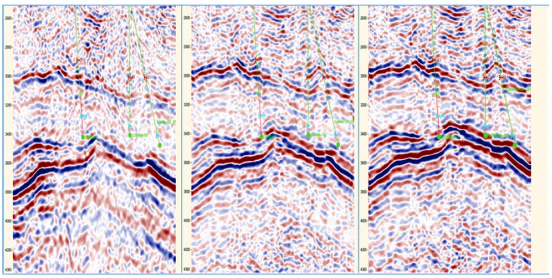
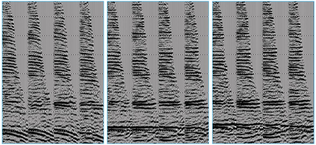
The criteria for a successful iteration are better focusing and simpler structure. Note in Figure 3 the sequence of depth images showing both the qualities described. Another important data review involves the CIP gathers. Figure 4 demonstrates that the goal of tomography is to achieve relatively flat gathers within the target velocity resolution. Perfectly flat gathers would likely yield non-geologic velocities and potential instability in the tomographic solutions.
After isotropic depth imaging, depth calibration with formation tops consists of vertical corrections to the depth volume to tie the well control. For anisotropic depth imaging, calibration is more intricate as the formation tops are used as constraints in the vertical velocity field and the anisotropic parameter estimates during the iterative updates. Therefore, another important interpreter goal is:
- Database Validation: Establish consistency between formation tops and seismic horizons
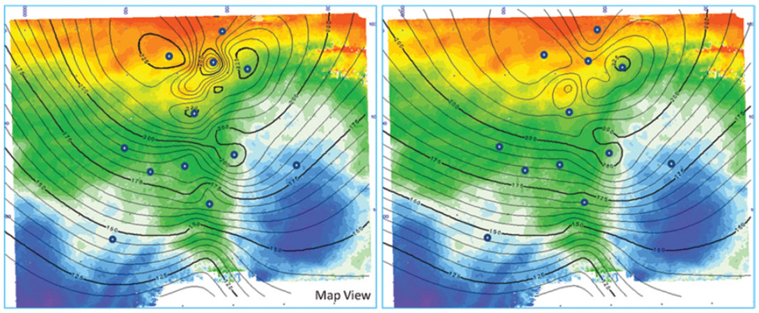
Figure 5 shows depth-difference maps (seismic horizon depth minus formation tops) before and after editing. The map on the left contains local “bubbles” indicating problematic seismic ties to the formation tops. Corrections were made to the KBs, deviation surveys, and interpreted tops resulting in the smoother map on the right. Since errors in the database result in errors in the anisotropic parameters, early detection prevents the formation of a compromised depth image.
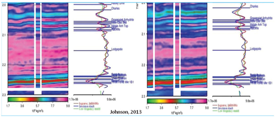
Stable depth-imaging results allow for the optimal extraction of information from the seismic. After depth calibration, they are also ideally suited for input to inversion and reservoir modeling. Figure 6 shows prestack azimuthal inversion to Fast and Slow Shear Impedance. High-resolution inversions yield the details needed to better define the combined effects of lithologic variations (density, incompressibility, and rigidity) and directional fracturing and/or stress fields.
In summary, the translation of the seismic response to measurements of significance to drilling and development engineers remains a challenge in the drilling-dominated “resource plays”. Depth imaging is established as the only viable approach to creating attributes that truly mitigate risk. It is the interpreter’s responsibility to guide this process.


Join the Conversation
Interested in starting, or contributing to a conversation about an article or issue of the RECORDER? Join our CSEG LinkedIn Group.
Share This Article