CHAPTER ONE: The Setting
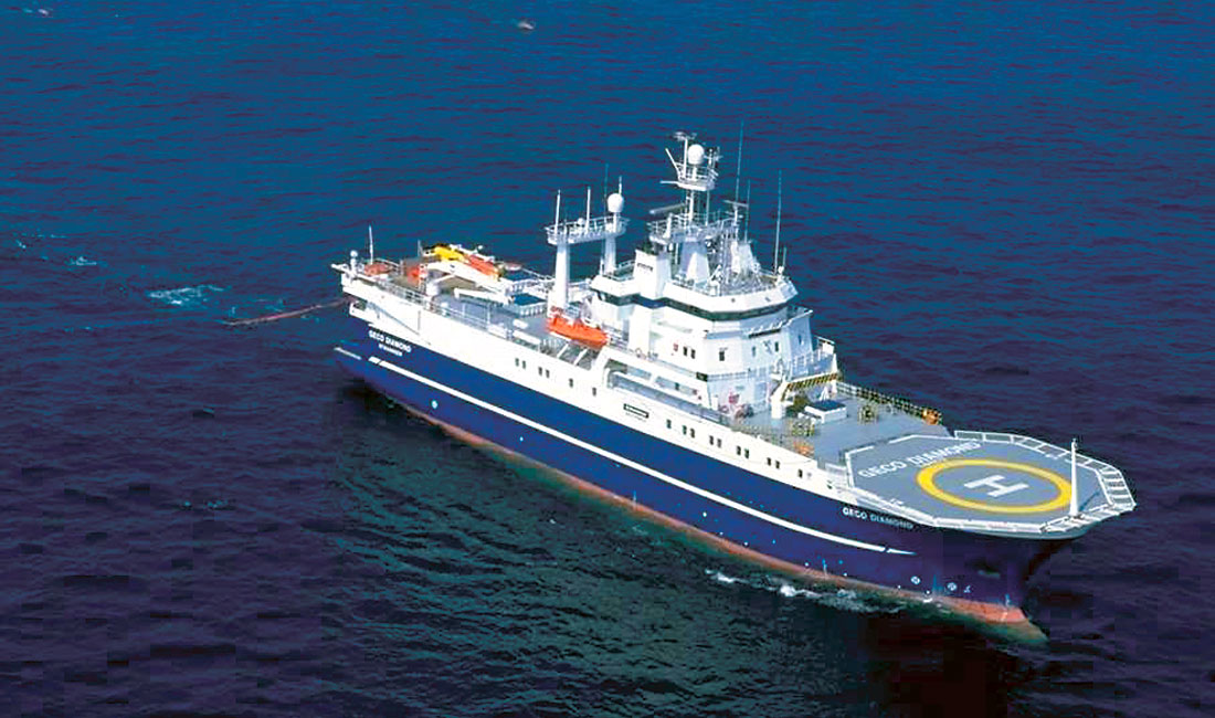
In December of 1901 Guglielmo Marconi transmitted the first transatlantic signal from Cornwall, England to St. John’s Newfoundland. The signal was received at a site that has come to be known as Signal Hill, from where you can overlook both the North Atlantic and North America’s oldest city, St. John’s of Newfoundland & Labrador. That singular signal would travel 2100 miles and in a way be a harbinger of future traffic, especially ship borne, that would frequent the famous port city. Approaching St. John’s by sea one spots the ‘Narrows’, literally the gateway to the harbour. Off to the starboard side you get a good view of Signal Hill, which has acted as a beacon to warn advancing ships of the rocky shores. It was June 1995 that the latest wave of offshore seismic exploration began. Over eight years ago both the crew of the MV Geco Diamond and a sizeable contingent from Calgary were collectively introduced to the capital city of Canada’s youngest province during a memorable screeching exercise. Screeching-in is the traditional manner for becoming an Honorary Newfoundlander. The traditional manner is quite often followed by a very forgettable following morning.


As the MV Geco Diamond was being tied up in St. John’s the crew could not help but notice the many grand churches that dominate the hillside. No doubt a comfort for many whose loved ones would make their living at sea and at worst claim membership in its tragic past. For the crew of the Diamond though, the churches would soon pass fro m sight, as the following morning was met with sailing orders. The challenge would be a 1600 square kilometer 3D survey northwest of Hibernia, utilizing 4 streamers and a triple source that would yield 12 subsurface seismic lines with every pass. A spring assignment in the unforgiving North Atlantic would indeed be a stern test.

CHAPTER TWO: The Vessel
Seismic vessels, while all having uniqueness, also have a great deal in common with one another. The uniqueness being a product of the year they were laid down, where they were constructed and most importantly the crew on board that ultimately defines the ship. Taking a look at the similarities first, we would find: some form of navigational control, seismic source, streamers with the attached hydrophones, and varying degrees of on-board processing or quality control.
Firstly, unlike earlier efforts at offshore exploration, navigational knowledge has made tremendous strides. At one time it was sufficient to know the location of the vessel while the positions of various other equipment was calculated as a result of it. Today, in a world that demands high-resolution 2D and 3D surveys not to mention 4D (time lapse 3Ds over the same area), a greater need for specificity exists. Using Global Positioning Satellites (GPS) and differential techniques, this part of the operation has made the greatest improvements. Solely from a seismic perspective the position of the source and receiver is important, the vessel is irrelevant.
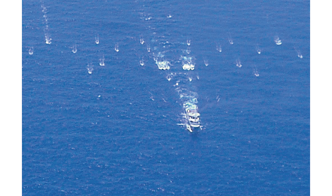
Secondly, we look at Marine Sources that too have seen changes. Previously, offshore exploration would subscribe to using a large airgun for the desired energy output. Today smaller airgun arrays have replaced the single source. The constructive interference of the various elements in the array is thus capable of achieving the farfield amplitudes that are required to image structures deep below the water bottom. It should also be noted that the array approach of using smaller volumes has the added bonus that they are less intrusive to the environment.
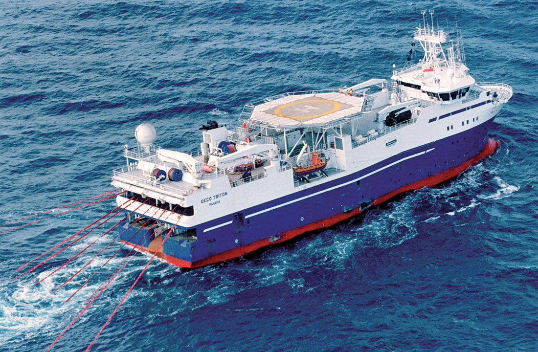
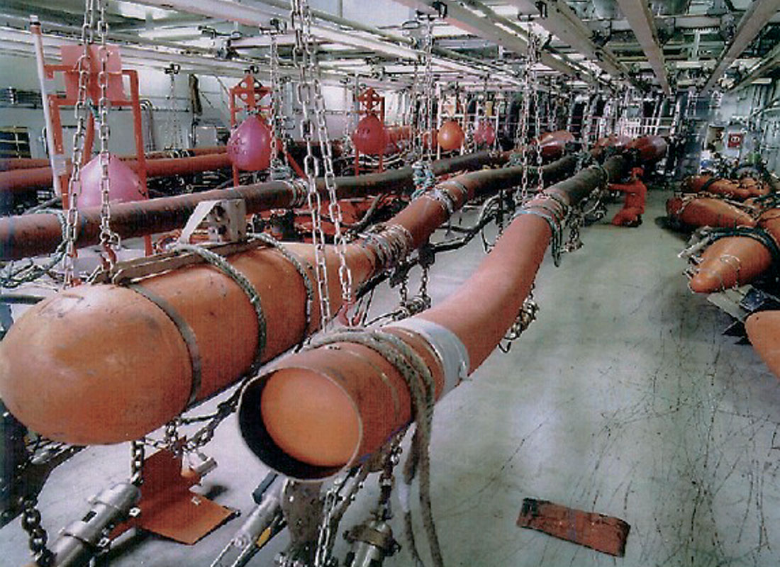
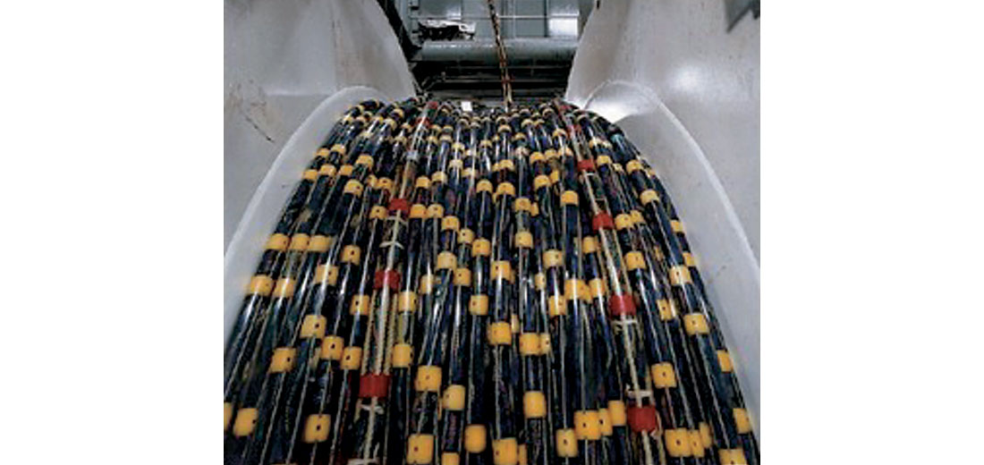
Thirdly, streamer technology, which traditionally garners most of the promotional publicity, has changed. From a single or dual streamer environment back in the 1980s, we find anywhere from 6-12 streamers being routinely employed today on a 3D survey. The back deck on a seismic vessel is a very active area while deploying this gear in a safe and efficient manner. With streamers having up to 200-metre separation, acquisition footprints have long ago eclipsed the one-kilometre width threshold. In length 3D spreads can stretch up into the eight-kilometre range, thereby yielding a total footprint area upwards of eight square kilometres. Aside from the footprint, the type of streamers has also undergone some changes. The type and amount of cable fluid have changed with the introduction of Solid and Q streamer technology. The more traditional streamers themselves underwent significant change to provide a more robust and durable material in confronting rough seas and even predatorial behavior by sharks that occasionally have taken a liking to chewing on seismic cable. Lastly, one need look at the deflector or towing technology that allows for the streamers to be pulled through the sea, all the while retaining the required cable separation. These devices allow for the separation while not significantly adding to the drag. Towing technology has seen an evolution from designs emulating fishing lures, to spread nets, to the current “Monowings” modeled after airplane wings.
The last major technology involves the on-board processing or QC capabilities. Today the Party Manager on board in conjunction with the Operator (Client) defines various thresholds under which the operation can proceed. Effectively, everything from the number of non-operating hydrophones to the signal to noise ratio is identified. If the vessel finds itself out of spec on any item that has been identified then operations revert from production to weather or technical downtime. Of greater importance is the matching up of the data traces (hits) with the subsurface binning. Here real time binning allows those on-board to monitor and keep track of cell coverage. If the number of hits falls below the project specifications then it is flagged as part of an infill program; infill being in effect the second pass to fill in all the coverage holes. An analogy would be the touch up work on a paint job ensuring all areas have sufficient paint coverage.
True on-board processing of course entails much more. In fact a decade ago some of the world’s largest data processing centers were located on seismic vessels. Here geometry and navigation can be merged and verified. Under the supervision of senior Data Processors the extent of data processing can go from “first look” volumes all the way to final time migrated data sets. Along the way various displays can be generated to ensure that the caliber of data being acquired is in line with the Geophysicists’ expectations. Rather than wait until the data volume hits the shore based processing center, the analysis can be undertaken on-board thereby providing an opportunity to modify acquisition techniques. Through satellite transmission anything from velocity analysis to final stacks can be sent back for the exploration team to evaluate.
In looking at the major components of a seismic vessel, as previously detailed, it is important to remember that there are two distinct entities operating both independently and in concert. This involves both the maritime crew as well as the seismic complement, both having unique responsibilities for the care of the ship or alternatively for the project at hand. In order for the vessel to operate in a safe and effective manner cooperation and mutual respect is mandatory. In the event adverse conditions at sea intervene, the Captain, who heads up the maritime crew, has complete and total command of the ship. In the ageless tradition of the sea he maintains total and unquestioned control.
CHAPTER THREE: The Regulators
East coast exploration effectively falls under the jurisdiction of one of three bodies. The National Energy Board (NEB) isn’t charged with administering issues offshore Nova Scotia or Newfoundland & Labrador. Instead, joint federal and provincial Boards have been commissioned to administer in the respective regions. In Newfoundland we find the Canada Newfoundland Offshore Petroleum Board (CNOPB), and in Nova Scotia we find the Canada Nova Scotia Offshore Petroleum Board (CNSOPB). To complicate matters we find a small corridor emanating out from St. Pierre and Miquelon referred to as the “French Tube” that is administered out of Paris, France. In order for an Operator (Oil & Gas Company) to commission exploration in either jurisdiction they need to work through the Boards. Through the CNOPB and CNSOPB parcels are nominated, posted, and leases awarded on a work commitment basis.
Once a lease has been awarded to a Lessee a five-year term commences whereby the Lessee must fulfill his work commitment (an extension can be granted for drilling purposes). This normally involves acquiring a seismic survey to assess any prospectivity on the lease. Once a decision has been made various other Regulatory agencies become involved. The Canadian Environmental Assessment Act (CEAA) oversees all activities on Canada Lands. The Operator will be responsible for undertaking a study to verify that there will be no negative consequences of the planned work. If approved, it will be back to the respective Board. Whichever Board is involved will require that a Canada Newfoundland (or Nova Scotia) Benefits plan be filed. Through expressions of interest all qualified local contractors will be afforded the opportunity to participate.
Along with the Benefits Plan a number of other submissions are required; these would range from the Project description, Proof of Financial Responsibility, Declaration of Fitness, Safety Plan and an Emergency Response Plan. The latter is a collection of measures that chronicle what will transpire in the event of an unexpected incident. With all these elements in place we are ready to begin acquiring the survey. Before we begin work though, we need to take a look at another group of stakeholders.
CHAPTER FOUR: Academia and the NGO’s
Sitting outside the federal and provincial regulators we find the non-governmental organizations (NGOs). This broad categorization includes many groups. Here we will take the liberty of including the world of Academia and various other scientific bodies. Their involvement is welcome as they certainly contribute to basin studies as well as have an interest in the seismic that is acquired. Institutions such as Memorial University in St. John’s and Dalhousie in Halifax provide valuable research through their commitment of time and resources.
Generally when referring to NGOs we are looking at the role of the environmental lobby. Progressively over the last few years some organizations have assumed a very negative perspective on seismic studies. Regrettably, some claims against the Industry have been made that have little bearing in fact. The confusion over naval sonar and the seismic source is certainly one in the forefront. Aggressive and possibly harmful sonar employed by various naval forces utilizes frequencies in the kilohertz range, far removed from the intermittent frequencies used in seismic testing. In spite of the volume of testing that has taken place at a global level, more is demanded. The fundamental issues dealing with the fish and marine mammal populations today occupy a presence equal to any other issue in offshore exploration. Courses are provided in species recognition to those on-board to supplement the role of third party Observers. Protocol has been established with respect to ramp up procedures as well as shut down scenarios in the event marine mammals are sighted. No longer is the “E” component in a Quality, Health, Safety, and the Environment (QHSE) program dwarfed by the other three elements.
Despite the testing and accommodation that has been undertaken by the seismic industry a struggle to justify its activities continues. Hopefully, a true partnership will evolve recognizing both rights. Membership in the seismic industry certainly doesn’t preclude membership in the greater cause directed towards the health of our oceans and rivers.
CHAPTER FIVE: Acquiring the Survey
When a seismic vessel has been selected to acquire a survey its activity fits into one of three categories. Mobilization constitutes the time that it takes the vessel to arrive on scene, complete the equipment deployment phase, and record a nominal amount of production to ensure everything is up and running. The amount of time can vary depending on where the vessel is coming from. Typically a 1-1/2 week period could be assumed from the Gulf of Mexico. Deployment also is highly variable and can range from 3 to ten days depending on the number and length of streamers. Additionally, water temperatures and salinity can have an impact on the streamer balancing during the deployment phase. Once the mobilization has been completed we move into the Production phase. Here on either a turnkey or day rate basis, the vessel and crew will acquire the prospect within the acceptance criteria spelt out in the contract. This is normally the most time consuming phase and operations are on a 24-hour basis. As a benchmark with weather, technical downtime, and infill excluded, 40% becomes an enviable target for production efficiency. The final phase of the operation becomes Demobilization. Here all the gear has to be retrieved from the sea and the vessel departs for its next assignment. Targets are established for both mobilization and demobilization to gauge the efficiency.
Similar to its Land cousin, all offshore surveys are not alike. While the inline sampling interval is fairly standard at 12.5 meters there are differences in the crossline sampling. With a finite number of streamers available the tighter the sampling in the crossline dimension the longer it takes to acquire. The time consumed has a direct bearing on the cost of the survey itself. A vessel sail line is analogous to a stroke with either a wide and coarse paintbrush or a narrow fine one. We can cover the wall much faster employing the wide brush than the narrow one.
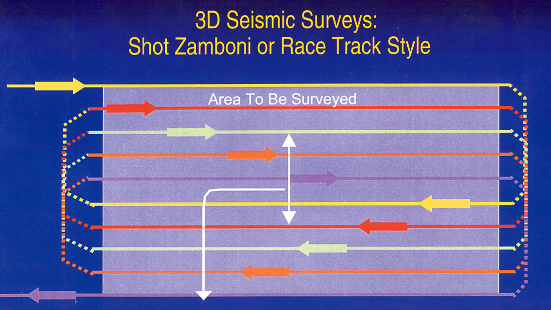
The manner in which the data is collected is often referred to as the racetrack approach. In Canada a much better analogy would be how the Zamboni machine cleans the ice at a hockey rink. Here the Zamboni makes one pass right up the middle and returns along the outside edge, progressively moving from the outside swath towards the middle and the middle swath towards the other outside edge. Once completed the process is repeated by moving over to another rink that sits adjacent to the one completed.
This approach is responsible for acquiring primary coverage. Once completed, a secondary or a series of infill passes are made. Ocean currents have an obvious impact on how faithful the streamers are in adhering to the pre-programmed sailing coordinates. The amount of infill is a product of how rigid the binning specifications are along with overall sea conditions.
Along with the seismic vessel itself a couple of additional ships may appear. From time to time a supply vessel will show up to transfer provisions and even fuel. In Canadian waters the supply vessel will be contracted from a local sub-contractor. The other vessel that may be required is referred to as an escort vessel. As the title suggested the role taken on by this ship would be to alert other traffic concerning the streamers and the acquisition footprint that the seismic vessel is towing. Normally, sharing of the seas between other seismic boats and the public at large is arranged in advance, but the escort vessel acts as a secondary line of safety.
With the completion of the project the task shifts to forwarding all data shipments and transporting any Client representatives to shore as expeditiously as possible. Noting these tasks highlights the significance helicopters and safety have to play in an offshore operation. It is inefficient and too slow as mentioned, to depend on port calls to bring provisions and fuel on-board. With respect to personnel transfers a seismic vessel is well versed in the role a helicopter has in its operation. Twin-engine helicopters are needed to ferry personnel in and out on a routine basis and even more so in an emergency case. In the case of the latter, with full gear out, steaming to port would take far too much time. With the potential for a medivac situation always a possibility, albeit a highly mitigated one, the on-board Medic, helicopter personnel, and shore based medical support must work in a planned and rehearsed fashion. This is especially critical, as seismic operations seem to share those months when some of the worst fog rolls in.
CHAPTER SIX: The Setting II
With the turn of the century the majority of the 3D work shifted to the Nova Scotia Shelf. Along with St. John’s, Halifax has shared the role as the staging base for offshore exploration. Entering Halifax Harbour can be an unforgettable experience. Truly a world-class deep-water harbour, it has served Canada well. During the last world war along with Bedford Basin, it became the staging point for the legendary Atlantic convoys. For a short while after the war it was also home to the world’s third largest navy. Today the Canadian Navy still calls Halifax its main base but has a decidedly more modest presence. On the top of downtown Halifax one finds the Citadel. The Citadel was built by the Royal Navy as part of a global network of military bastions. It is from the Citadel itself that you can look down on the majestic harbour and onto Georges Island. During the war unfounded rumours spread that Churchill, the British Prime Minister, had stored the British gold in the inner confines of the Island. Despite the lack of gold it has no lack of charm.
For the exploration community over the last handful of years Halifax has become the staging point for a tremendous amount of offshore seismic activity. This has ranged from the shallow waters in and around Sable Island itself as well as deep-water exploration undertaken hundreds of kilometres from Halifax. Sable Island itself was the site for an Ocean Bottom Cable (OBC) survey in 1996-7. The surveys have ranged in size from a few hundred square kilometres to some in the 3,000-4,000 square kilometre range.
On June 2000, the MV Geco Triton, the second largest vessel in WesternGeco’s fleet, would pull into Halifax harbour. This would mark the first of three visits the Triton would make to Canada prior to 2003. During that period it would establish a Canadian towing record of 12 streamers by 6 kilometres. It would later that year set sail for its own Perfect Storm in the Flemish Pass and provide lifelong tales for all aboard. It was also during that port call that the Triton sailed alongside HMCS St. John’s. The St. John’s is part of the Canadian Navy’s new frigate fleet. Both vessels bring a gross tonnage in the 4,000- 5,000 range and were headed out to sea. Granted while the principle task at hand is decidedly different, both share ability for underwater remote sensing. For the Triton and other seismic vessels best wishes are always extended, by those ashore, for its quest to expose the energy wealth all hope reside off Canada’s eastern shores.
The rewards for all involved in offshore exploration are obvious. A well-deserved night in Halifax awaits those who work on-board the seismic vessels, a port city with no shortage of nautical tales and an equal number of pubs to tell them in.
CHAPTER SEVEN: The Next Generation
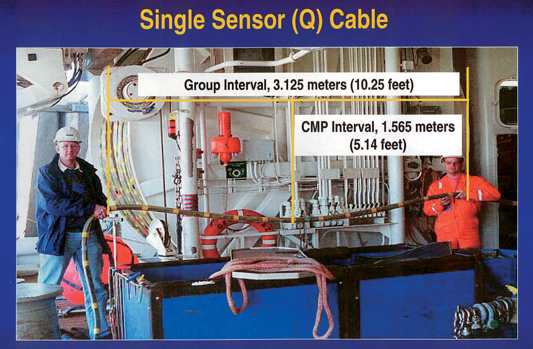
Never satisfied with existing technology the seismic industry has continued to make improvements. One of these was the introduction of Q-Technology. Here the architects of the new seismic system aspired to remove existing barriers. The first dealt with single sensor recording. Rather than accept whatever group interval was onboard the architects instead adopted a digital hydrophone at each sensor point. Whatever array was determined most appropriate could be selected in the processing center rather than some hardware limitation that came with the vessel. This flexibility allows for a number of volumes to be generated depending on the resolution required.
The second innovation was a fully integrated positioning network. Here there would be no interpolation or projection as to each node’s position on the sea. In effect an acoustic network that would yield sub-meter accuracy. If single sensor recording were to have any value it would have to be in a world where a trace’s position was precisely articulated. Any misplacement of a trace as a consequence of navigational error would only lead to smearing within a bin. If the objective was higher resolution trace location was imperative.
The third arm of the new system was a calibrated marine source. As more and more of the seismic in the world is acquired for development purposes a corresponding need to understand the reservoir exists. To fully understand the reservoir then, a need for 4D will be present. To evaluate the reservoir the seismic must be consistent from one survey to the next. All differences must relate to changes in the reservoir not the recording system. Here the confidence in recorded near-field signatures as well as far-field signatures becomes critical.
The last of the four innovations is streamer steering. The ability to control the streamers position in the x, y & z axes has tremendous benefits. The most obvious benefit was a reduction in the amount of infill. It also allows for the seismic vessel to continue working in rougher seas. Quite simply the streamers will be lowered further below the surface currents. If the sea conditions i m p rove the streamers will be raised. Also the repeatability specifications needed for 4D seismic require the steerable streamers to maintain uniform separation all down the entire streamer spread. Typically, without steerable streamers, the streamers bow outward or inward with different currents pushing and pulling them. This makes repeatability of 4D seismic next to impossible in marine. This remote ability allows for surveys to be acquired closer to design specifications and in a shorter time frame. Finally, another benefit from the ability to steer the streamers is related to QHSE. The fewer tangled cables the crew has to contend with the safer the operation on the back deck and to the environment (cable fluid leaks during tangles and equipment lost at sea). This reduces the need for zodiacs or other smaller craft to undertake work on the streamers.
CHAPTER EIGHT: Back to Calgary and Shore Based Data Processing
With all the regulatory compliance and high seas adventure behind us it is time for the real work to begin. This at least is the opinion of the Data Processing profession. A relatively small team of geoscientists will take charge of the data set. Their objective will be to take literally hundreds of high-density field media and condense it down into one or two. To accomplish this feat the field data will pass through three distinct phases.
Firstly, the Project initialization phase is undertaken. Here the shore-based team will liaise with the On-Board Processing team. Essentially the shore-based group will undertake a knowledge transfer in order that nothing will be lost in the transition. Knowledge that has been garnered at sea will be conveyed, often in person, to ensure the final data processors hit the ground running. Moving on, the Marine Processing Supervisor will establish a timeline and jointly engineer a collaboration environment with the Interpreter or Interpretation team. For the processing to be successful the two need to work as closely as possible.
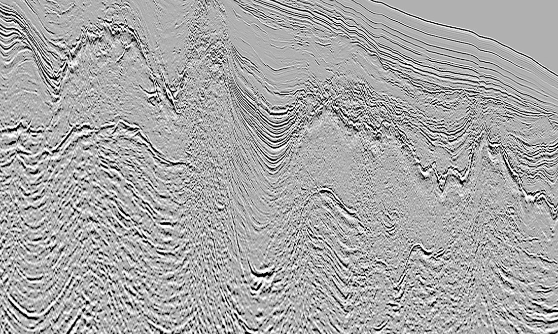
Secondly, the data processing will move into the Production phase. Here, all the basic wavelet pre-processing will be decided upon. Albeit, while all parameter selections are important some are more important than others. In the case of Canada’s east coast a major focus will be placed on velocities, demultiple approaches, and overall imaging. The issue of velocity field determination and demultiple strategies are related and require the aforementioned Interpreter-Processor collaboration. The Canadian east coast possesses a very rugose and hard water bottom. Decisions reached here have a huge impact on the final product. It is also in the imaging arena that dramatic changes can manifest themselves. Here, with a variety of pre-stack time and depth migration algorithms available and PC cluster technology for horsepower, what was costly and time consuming a decade ago is standard today. Additionally, full cycle time has been attacked. A decade ago turnaround expectations on a 1,000 square kilometer 3D survey would have encompassed the better part of a year. Today the expectations are in place to deliver within a 3-month timeframe.
The last phase can be described as Delivery. While all the field data will be archived, the final processing will be defined not only in terms of final stacks. Other deliverables may include attribute analysis processing. A volume with all the final velocity fields itself will be produced. This potentially may be used in the area of pore pressure prediction. Also a comprehensive processing report will be composed chronicling the information gathered as well as decision criteria in deriving the final products. Yet, as many processors can attest, while we can see the completion of the first two phases discussion and additional requests sometimes go on for years!
It is at this point that our narrative comes to a close only to be repeated again, hopefully with the knowledge gained to be i m p roved upon. As with Guglielmo Marconi’s successful experiment of over a hundred years ago our industry has more work to do before perfection is reached. Newfoundlanders themselves could greatly assist the process by investing in the Screeching-in process itself. Anything that would remedy the morning after near death lamenting would be a great start!


Join the Conversation
Interested in starting, or contributing to a conversation about an article or issue of the RECORDER? Join our CSEG LinkedIn Group.
Share This Article