Introduction
In June 2001, Gijs Vermeer was invited by the CSEG RECORDER to look at the future developments in seismic acquisition. It was a rather difficult task, considering the seismic industry collapse in 1999 and the severe cuts in seismic industry research and engineering following a cumulative minus $2 billion free cash flow for seismic contractors in year 2000 (IAGC paper in The Leading Edge, January 2003). At the time of this writing, when oil prices are over $60 a barrel, and oil and gas demand is steadily increasing, and when oil companies have difficulty finding available seismic vessels, I feel more comfortable in looking at recent and future developments. I will look at both aspects of marine acquisition: acquisition technology and acquisition techniques, including survey design. I have included examples to illustrate different technologies and techniques, and I thank Chevron, Fairfield, I/O-GX, Total, and WesternGeco for permission to show these examples.
Recent developments
Marine acquisition can be separated into towed-streamer acquisition and stationary receiver acquisition. Stationary receiver acquisition can be performed with ocean-bottom cable (OBC) systems or with node systems. Under stationary receivers I also included a non-seismic marine acquisition technique, Controlled Source Electromagnetic Method (CSEM) that has similarities with the node system acquisition. In spite of the difficulties our industry went through in the last five years, developments were made in both, towed and stationary receiver systems.
Towed-streamer acquisition
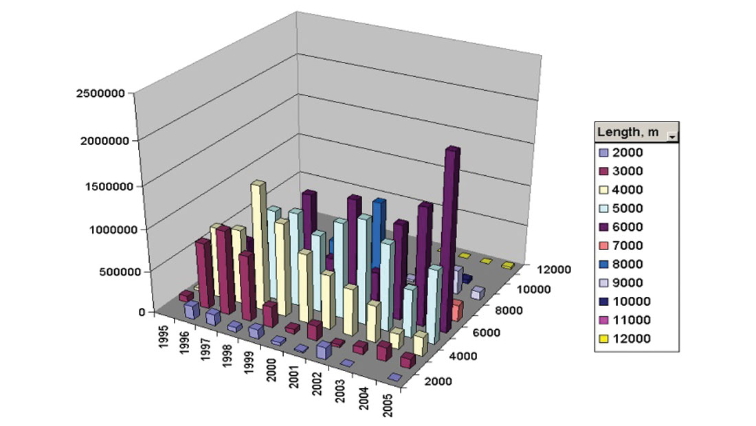
The trend over the past decade in towed streamer acquisition has been to increase the streamer length and the number of streamers being towed. Prior to 2000, most surveys were acquired with streamers shorter than 5000 m. In the last five years, an increasing number of surveys have used streamer lengths between 6000 m and 12000 m (Figure 1). This trend probably will continue in the future as a response to geophysical requirements for increased offsets and improved crossline sampling.
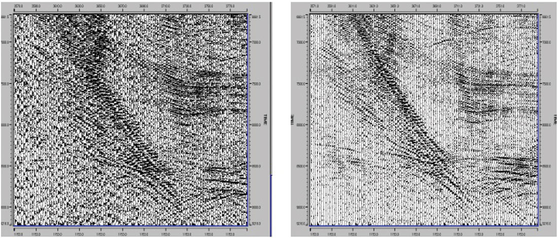
The solid streamer was introduced in 1997; it was used exclusively by one contractor for several years. However, other contractors have now adopted it. Instead of the traditional oil-filled tube, the streamer is composed of solid composite materials. This design has some operational and geophysical advantages over conventional oil-filled streamers. In high sea states solid cable has proven to be quieter than conventional streamers, especially on the near-offset (Figure 2).
Towed-streamer marine acquisition was advanced by the introduction of the Q-Marine* acquisition system by WesternGeco. The main features of this system are: point-receiver acquisition, a new receiver positioning system, streamer steering, calibrated receiver measurements, and a calibrated marine source. The Q-Marine system can deliver seismic data with improved signal-to-noise ratio, greater bandwidth, reliable amplitudes due to calibrated sources and sensors, accurate positioning of the receivers along the streamers, and steerable and repeatable positioning. Curtis and Eiken discussed in detail the benefits of the Q-Marine system for 4D application in the Expert Answers paper published by the CSEG RECORDER in the June 2004 issue. In this article I have included examples to illustrate other geophysical benefits of Q-Technology*.
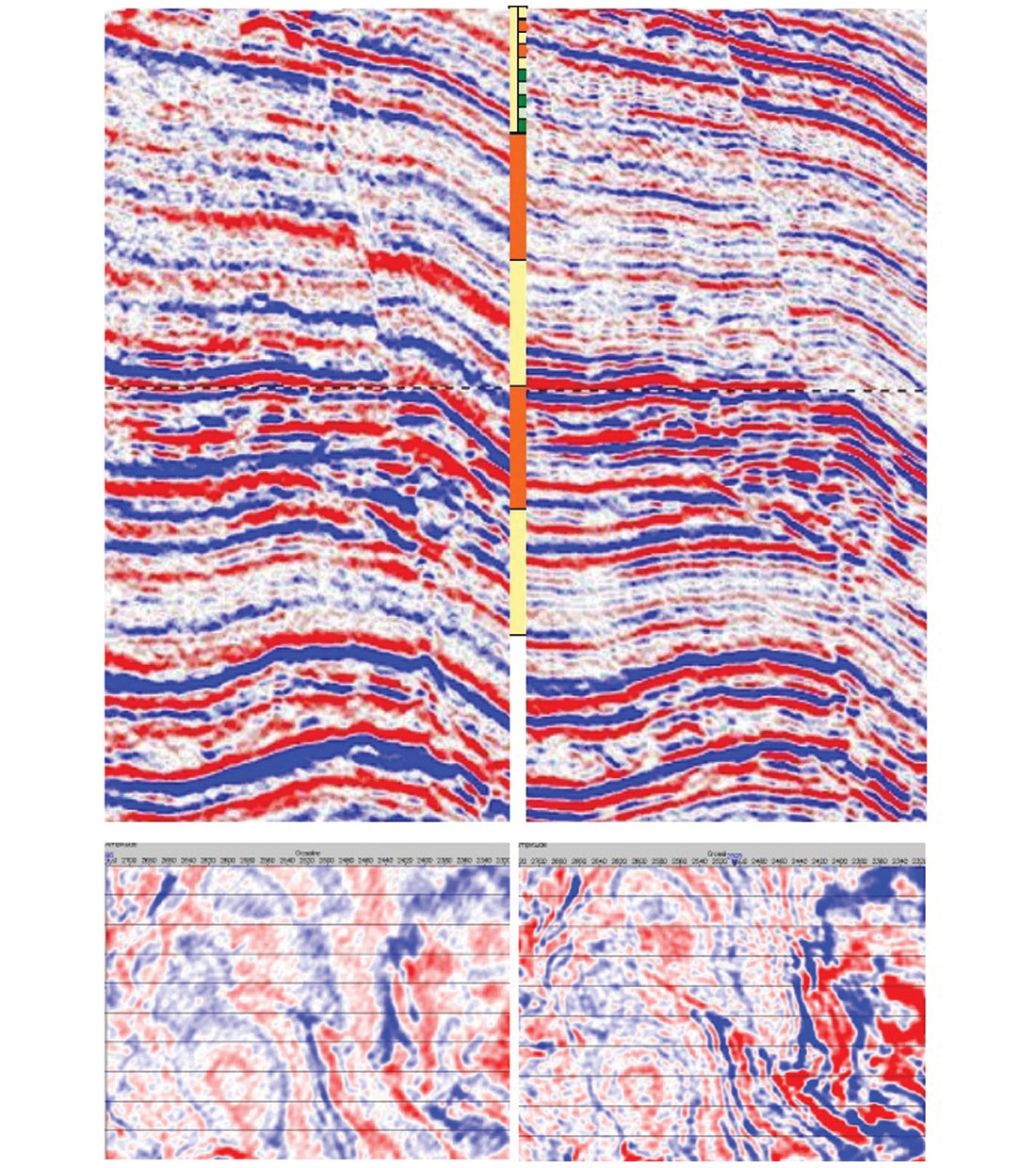
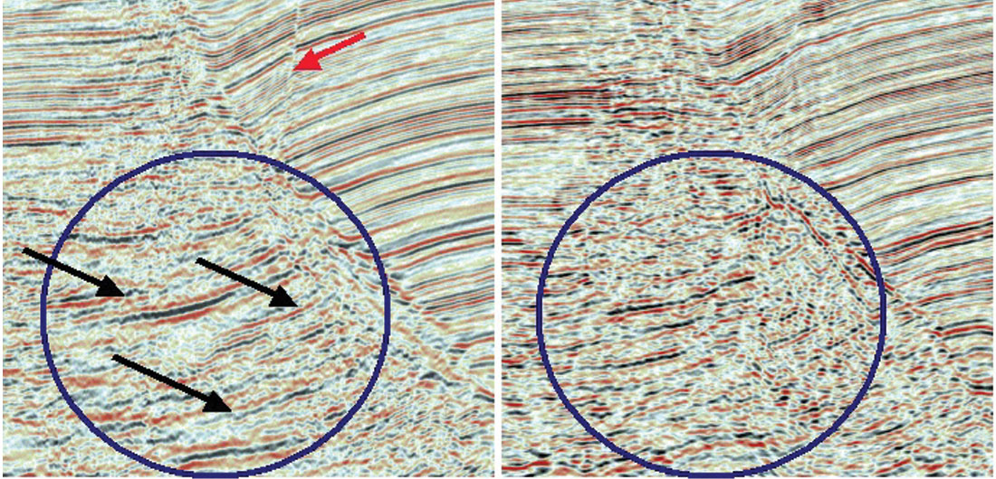
The first example, provided courtesy of Chevron, is a comparison between a conventional survey and a Q-Marine survey and illustrates the improvements in seismic resolution found from using Q-Marine data. The conventional high-resolution survey was acquired in the Lower Congo Basin in 1997 and reprocessed in 2002, and the Q-Marine survey was acquired and processed in 2003. The acquisition parameters for both surveys are listed in Table 1. Figure 3 shows a comparison of cross sections and timeslices from the conventionally acquired heritage dataset (Panel a left) and the Q-Marine dataset (Panel b right). The survey objectives were to map thin sand units associated with turbidite sand channels. The improved definition of faults and improved resolution of the channel at the target level can be clearly seen on the Q-Marine dataset.
| Acquisition parameters | 1997 “High resolution” | 2003 Q-marine |
|---|---|---|
| Table 1. Acquisition parameters. | ||
| Source depth | 4 m | 3.5 m |
| Source separation | 50 m | 37.5 m |
| Streamer length | 6 x 2000 m | 6 x 5000 m |
| Streamer separation | 100 m | 75 m |
| Group interval | 12.5 m (15.45 array) | 3.125 m (single sensors) |
| Streamer depth | 5 m | 4 m |
| In-line bin size | 12.5 m | 6.25 m |
| Cross-line bin size | 25 m | 18.75 m |
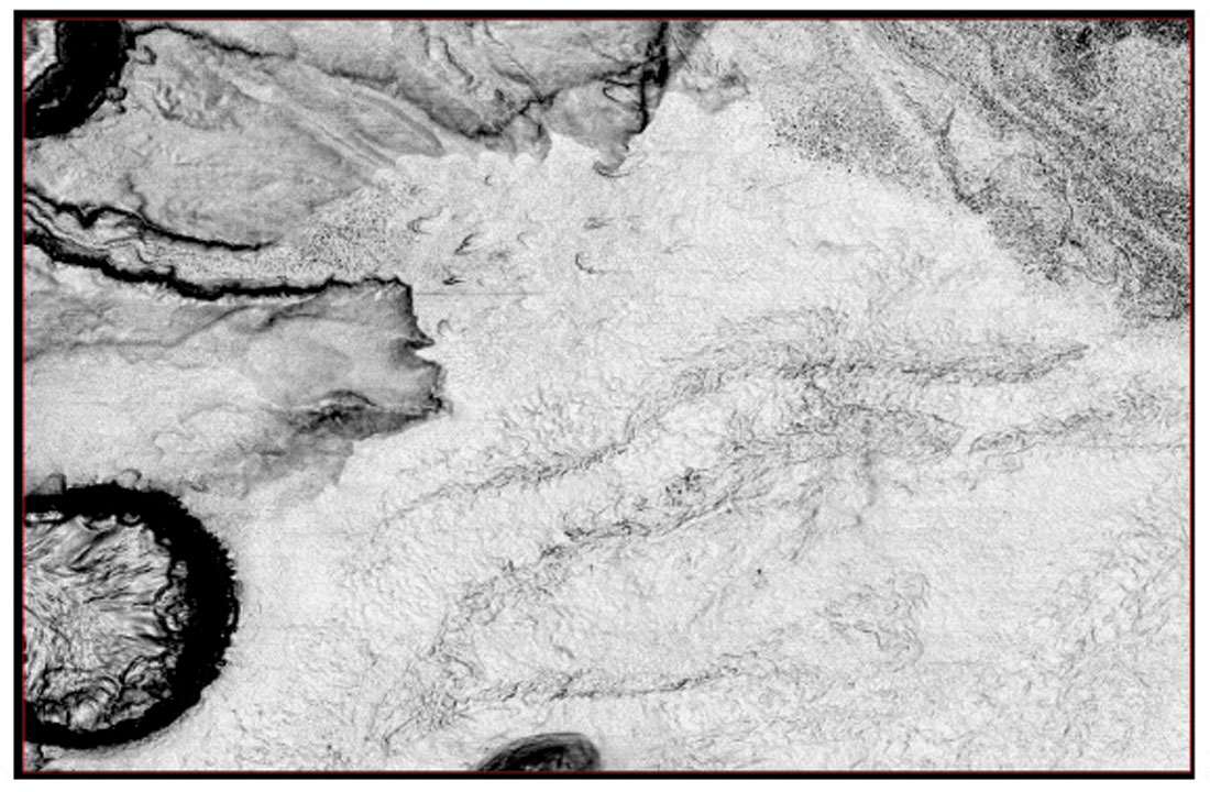
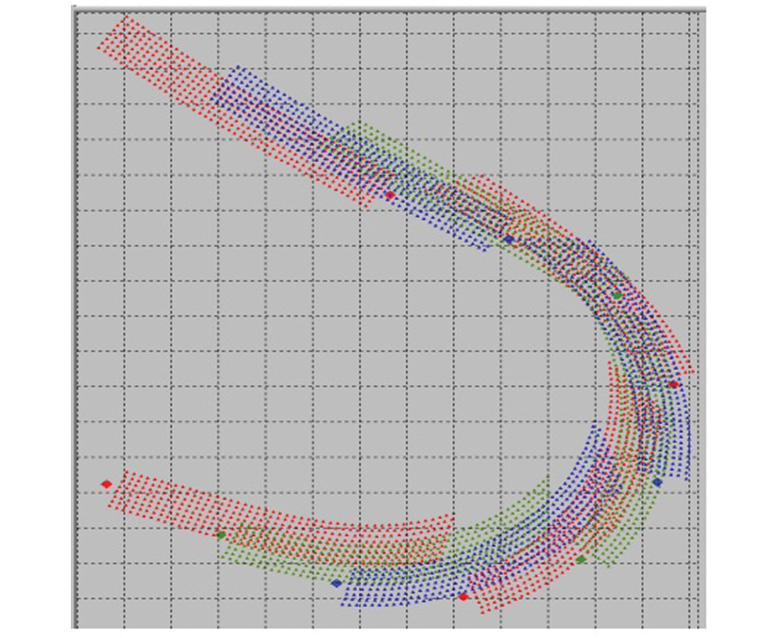
The second Q-Marine example illustrates the benefits of streamer steering. Streamer steering allows maintaining constant streamer separation, even in the presence of strong currents (Figure 4). The effect of constant streamer separation is more uniform offsets and azimuth distribution in the crossline direction and this reduces the acquisition footprint. Figure 5 shows a seabed dip map extracted from final processing of a Q-Marine survey in the Mississippi Canyon area of the Gulf of Mexico. The Q-Marine survey was acquired with eight streamers, 8 km in length, 100-m separation, and a dual source; the seabed dip map shows no evidence of acquisition footprint.

Stationary receiver acquisition
Two new 4C ocean-bottom cable systems were introduced in 2004: Q-Seabed*, introduced by WesternGeco, and VectorSeis Ocean, introduced by I/O. These new systems are characterized by improved vector fidelity, improved sensor coupling, and improved frequency response of the motion sensors. Conventional geophones in previous-generation OBC systems are replaced by geophone accelerometers (GAC) in Q-Seabed systems and by digital Micro Electrical Mechanical Systems (MEMS) accelerometers in the VectorSeis® Ocean system. In comparison with conventional geophones, these new sensors have an improved frequency response for the low- and the high-frequency end of the spectrum as illustrated in Figure 6 for the GAC and in Figure 7 for MEMS.
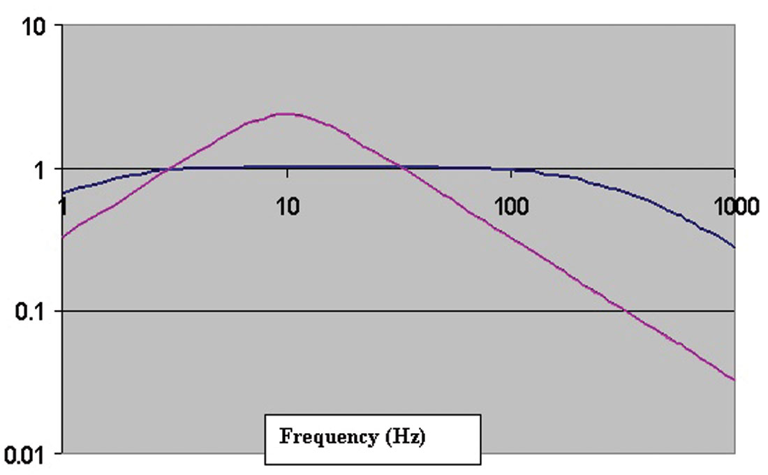
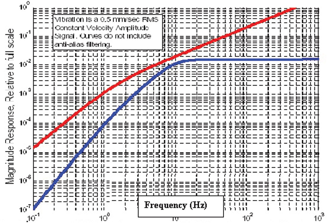
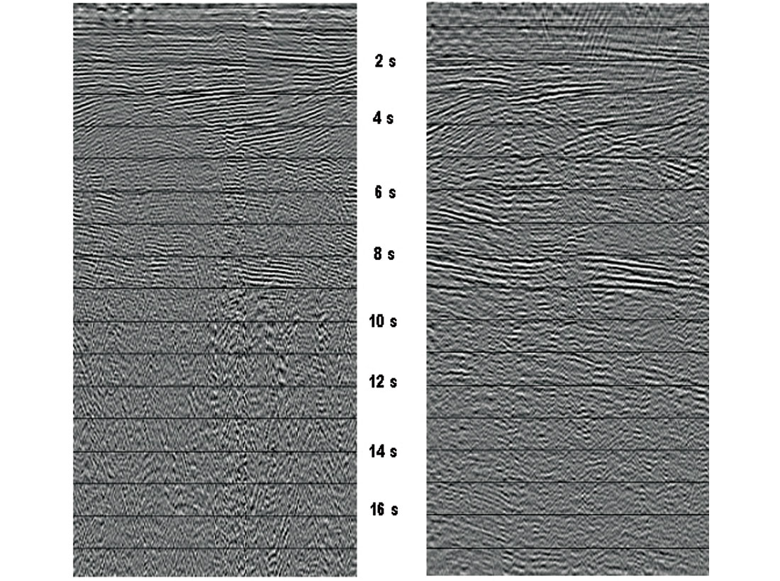
Figure 8, courtesy of Enron Oil and Gas, shows a comparison between a PZ section from a 2D swath acquired with the Q-Seabed system offshore Trinidad in 2004, and a towed-streamer section extracted from a 3D cube acquired in 2003. The OBC section has better fault definition, improved imaging below the major growth fault, improved event continuity, and less multiple contamination of the target. Figure 9 shows a PZ section recorded by the VectorSeis Ocean system in the Gulf of Mexico and a towed-streamer section. Both datasets were filtered with the same bandpass filter defined by the four points, 1,3,6 and 9 Hz. The comparison shows the good low frequency response of the VectorSeis with coherent signal visible up to16 s.
Alternatives to the OBC cable systems are the node systems. Two new node systems, the Autonomous Reservoir Monitoring Seismic System (ARMSS), and the Z-system were introduced by Sercel in 2004 and Fairfield in 2005, respectively.
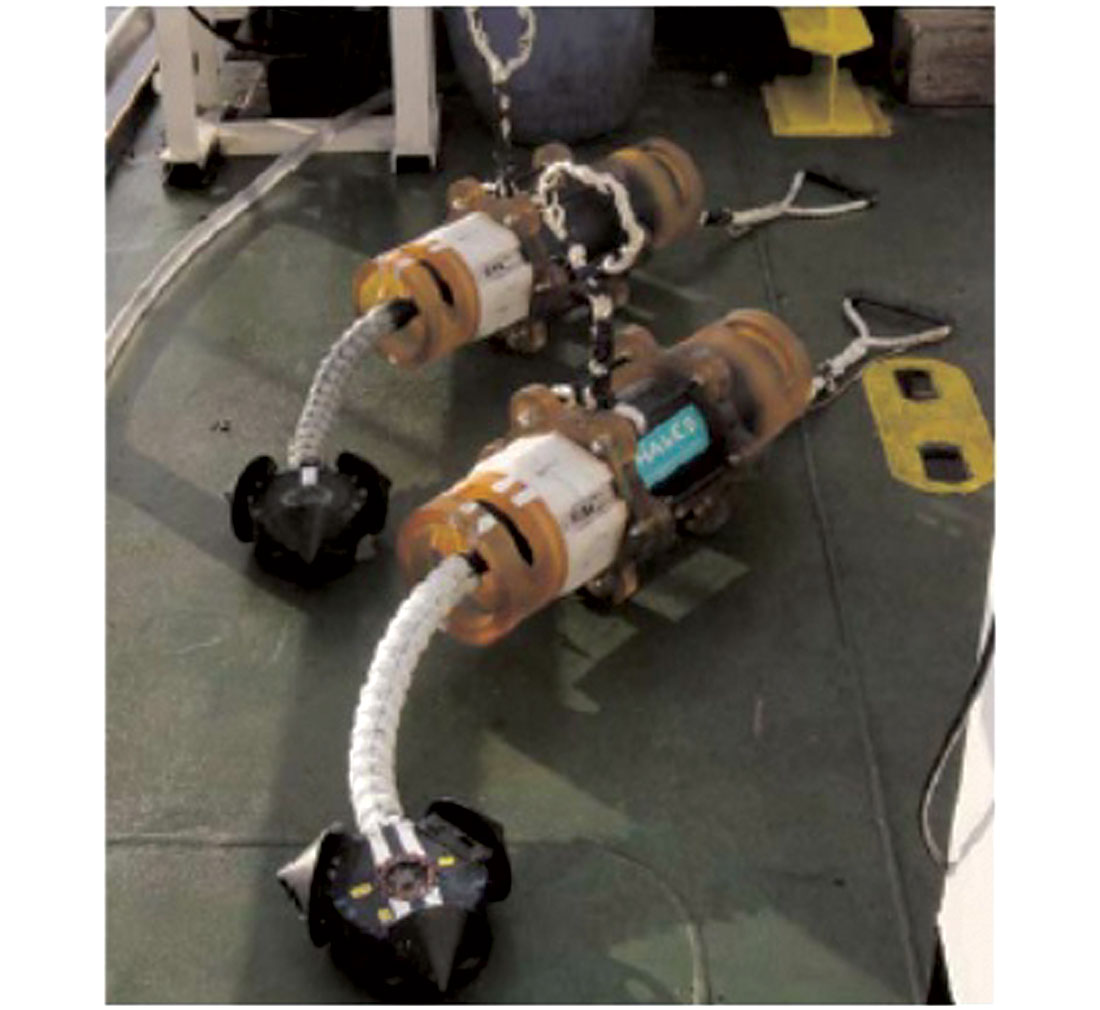
ARMSS is a fully autonomous seismic node that has the capacity to record 4C data for up to 45 days. The node (Figure 10) is deployed by a remotely operated vehicle ( ROV). The sensor compartment contains three fixed geophones in a Galperin arrangement. Outside the sensor compartment is mounted a hydrophone that is in direct contact with the water. Tilt measurements are performed by three accelerometers. A vibrating system is included to assure optimum coupling with the sea floor at the layout stage. A comparison between streamer data and node data was made by Total E&P, Angola during an experiment over the Girassol field, offshore West Africa (Granger et al., 2005). Five ARMSS nodes were deployed at 1300-m water depth. Final migrated data for streamer, hydrophone, and vertical geophone are shown in Figure 11, illustrating the good quality of the node data, which is similar to the streamer data. The experiment performed by Total proved that the combination of towed streamer acquisition and node acquisition is a practical method of acquiring seismic data in obstructed areas.
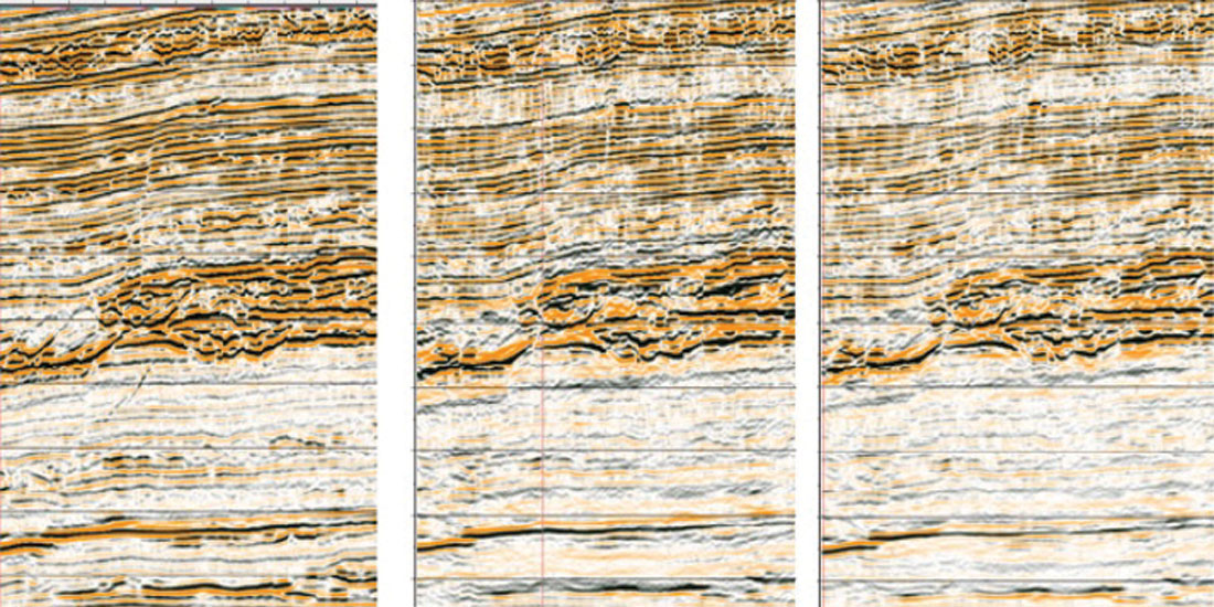
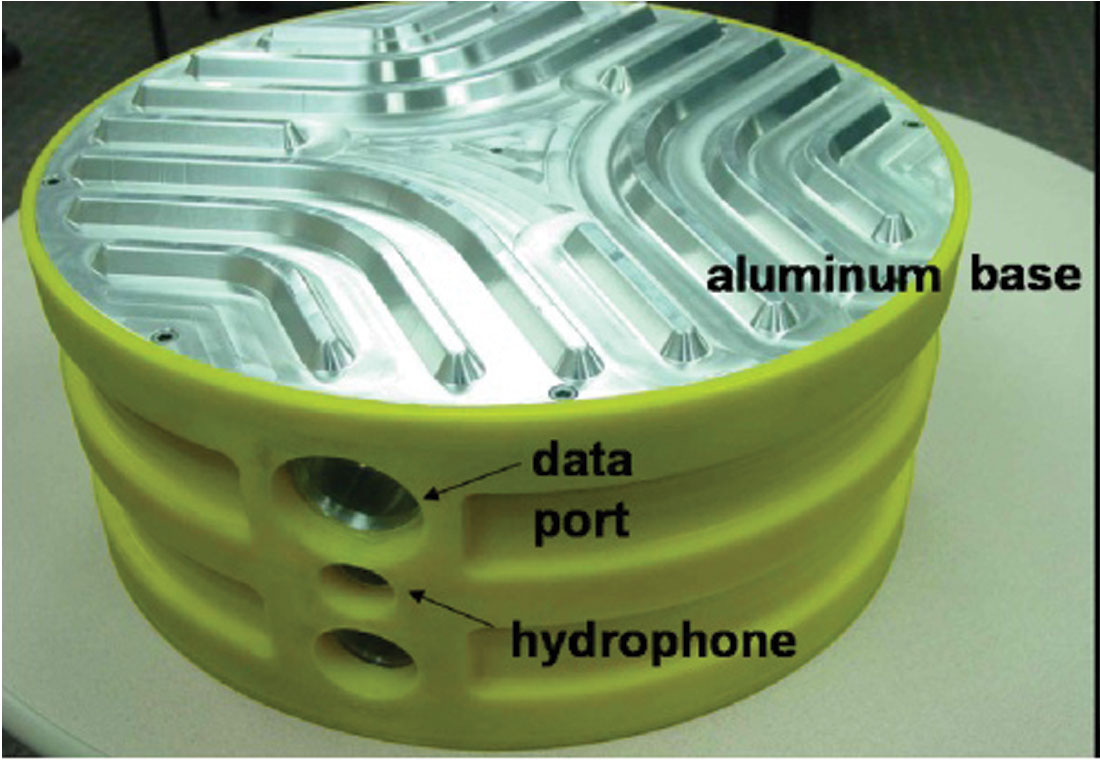
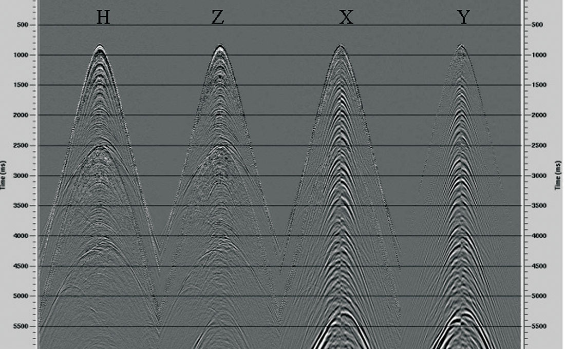
The Z-system contains three fixed geophones (not gimbaled), one hydrophone, the recording device, a very accurate clock, a compass, and a long-lasting battery (Figure 12). The nodes are laid on the seabed by a ROV and continuously record the seismic source signals until they are retrieved to download the data. Compass and tilt measurements are also recorded and used to determine orientation of each node. Figure 13 shows an example of hydrophone, vertical geophone and X and Y horizontal geophones data recorded during a test in the deepwater Gulf of Mexico, Green Canyon area (Docherty et. al., 2005). The common receiver gathers generated from 200 shotpoints show wide bandwidth, high signal-to-noise ratio vertical geophone data that are comparable with hydrophone data, and coherent PS converted energy on the horizontal geophones.
At the Valhall field, BP permanently installed the first 4C OBC system in 2003, as part of “The Life of Field Seismic” project, and it proved to be a step change in the use of seismic analysis in active reservoir management and operations (Kommedal and Barkved, 2004). With a permanently installed system, 4D analyses can be performed at more frequent intervals to allow monitoring of production changes and to optimize the depletion of the reservoir. In addition to 4D seismic data, other passive reservoir monitoring information can be collected during water injection, fracturing, and other reservoir operations.
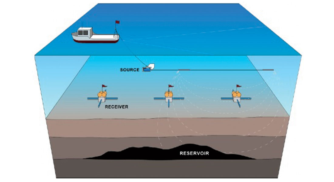
One marine electromagnetic (EM) method that has been used increasingly over the last three years is Controlled Source Electromagnetic Method (CSEM). An electromagnetic source is towed behind a vessel in deep water while maintaining a constant altitude above the sea floor. The EM receivers, which incorporate data loggers, are autonomous sea floor units deployed at pre-defined locations and record data continuously while the EM source transmits a continuous waveform (Figure 14). An accurate navigation system positions the sources and receivers. The new application that emerged recently for CSEM was direct hydrocarbon detection in deep waters. Unlike the seismic method, CSEM relies on large resistivity contrasts between hydrocarbon-saturated reservoirs and the surrounding sedimentary layers (Eidesmo et al., 2002).
Acquisition techniques and survey design
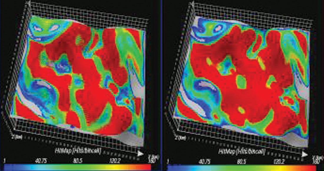
In recent years, the most remarkable thing that happened in marine acquisition is wide-azimuth acquisition to image complex targets, particularly subsalt. Under the generic name of wide azimuth I included multi-azimuth, wide-azimuth and full-azimuth surveys. Figure 15 illustrates the offset-azimuths distribution (rose diagram) for different types of wide-azimuth surveys. A multi-azimuth survey consists of several narrow azimuth surveys acquired over the same prospect, and typically requires one multistreamer multisource vessel. The acquisition of wide-azimuth and full-azimuth surveys requires one or more streamer vessels and two or more source vessels. The main benefits of wide-azimuth data are improved target illumination, increased signal-to-noise ratio due to high fold count and different azimuth contributions, and better multiple attenuation. Another important benefit is for fracture characterization studies. A 3D ray tracing target illumination comparison between a conventional marine acquisition and a wide azimuth towed streamer acquisition for a subsalt reservoir is shown in Figure 16 and this illustrates the improved illumination of wide azimuth survey. BP acquired the first wide azimuth towed streamer survey in the Gulf of Mexico in 2004- 2005 (Judson, 2005).

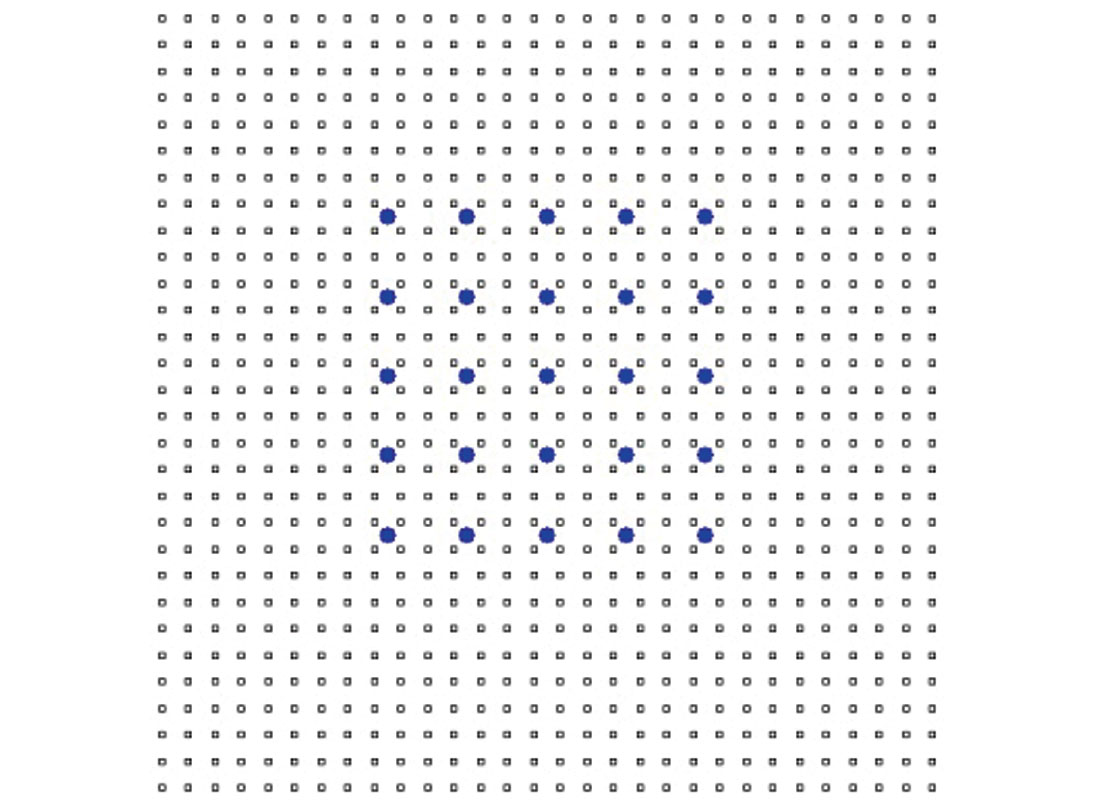
Full-azimuth seismic surveys can be implemented with the node systems, and this requires a regular grid of receivers (nodes) surrounded by a regular grid of source points (Figure 17). BP commissioned Fairfield to manufacture the Z-deep water node system and a full azimuth node system survey was acquired in the Gulf of Mexico over the Atlantis feld in 2005-2006.
A legitimate question could be asked: “When should a towed marine streamer system be used and when should an OBC system, node or cable, be used to acquire wide azimuth marine surveys?” If PS converted waves are required for reservoir imaging or reservoir characterization, an OBC system must be used. If P-wave imaging is required, the answer is not straightforward, at least at this time, when there is very limited experience in both cases. Some factors that have to be considered in the selection of the proper method, which ultimately determine the cost, are the number of azimuths required for target illumination, water depth, obstructions in the area, survey size, and the numbers of receivers that could be deployed in the water or on the water bottom.
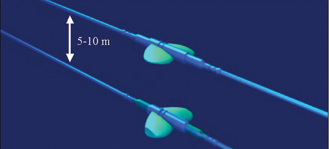
Q-Marine technology has also finally enabled the implementation of over/under streamer acquisition. This acquisition method was originally introduced in 1984 as a means to extend the weather window (Brink and Svendsen, 1987)). By deploying two streamers in the same vertical plane (Figure 18) at large depths, such as 20 m and 30 m, the swell noise is minimized and wavefield separation can be preformed to separate the upgoing wavefield from the downgoing wavefield (Sonneland et al, 1986). The upgoing wavefield is free of receiver ghosts and this improves the vertical seismic resolution by extending the seismic bandwidth at both the low and high ends. Conventional marine technology did not allow acquisition of reliable over/under streamer data due to limitations in the ability to control streamer positions. Q-Marine streamer steering, accurate receiver positioning and the fine receiver sampling of the system make it possible to accurately acquire and process over/under streamer data. The main benefits of over/under steamer acquisition are wider seismic frequency bandwidth, improved signal-to-noise ratio, and improved multiple attenuation. The separation of the upgoing and downgoing wavefields allows implementation of a new surface-related multiple attenuation method based on the deconvolution of upgoing wavefield by the downgoing wavefield (Kostov et al., 2004). To date, commercial 2D over/under streamer surveys have been acquired in the North Sea, Gulf of Mexico and West Africa.
A general trend in designing towed marine seismic acquisition is to increase the density of traces acquired per square kilometer. More rigorously defined, this means increasing the prestack migration fold (Moldoveanu et al., 2005). This aspect of survey design was discussed in the Expert Answers paper published by the CSEG RECORDER in June 2004.
Another important aspect of towed streamer survey design is to properly sample the seismic data to fulfill the processing requirements, particularly multiple attenuation. Surface-related multiple attenuation (SRME) is the preferred industry method because the algorithm does not require any information about the subsurface. However, the method requires having coincident receiver and source positions. For 2D applications, this requirement was not very difficult to fulfill, considering that source interpolation can be successfully done in processing to achieve a shot interval equal to a receiver interval. The SRME method evolved in the last couple of years from 2D to 3D, and it was proved that 3D SRME improves the attenuation of multiples in areas where the subsurface is more complex and 2D SRME assumptions do not hold. 3D SRME requires having equal source and receiver sampling in the inline and the crossline direction and also adequate crossline extent of the spread, or crossline aperture, to capture all relevant reflections. There is no design solution that allows an acquisition configuration that fulfills crossline sampling requirements. However, some acquisition solutions may be found to improve source crossline sampling, although the proposed acquisition could be more expensive than conventional streamer acquisition (Borselen et al., 2005). It is important to mention that, in the processing stage, data regularization is carried out before SRME in order to fulfill the sampling requirements. The success of the SRME method depends on how accurately the multiples are predicted from the data. The timing error in multiple prediction could be analyzed as a function of the proposed acquisition geometry and the feathering angle. Also, the required crossline aperture could be estimated for a particular geometry and a feathering angle. Based on this analysis, the acquisition geometry could be optimized to minimize the timing errors in multiple prediction (Moore and Bisley, 2005).
Future developments
My prediction of future developments is mainly based on the problems that we face with the current technology and that have to be addressed with new developments.
Towed-streamer acquisition
For 4D applications in areas with strong or unpredictable ocean currents like the Gulf of Mexico, offshore Brazil or offshore Indonesia, we do not yet have enough control of the spread, and receiver and shot repeatability could suffer. The focus will be on advanced spread control that could correct the streamer and source positions in the presence of large feather angles. An example of a source steering system for 4D applications was presented at the 2005 annual meeting of the Society of Exploration Geophysicists by Statoil (Naess, 2005): the self-overlapping system (SOS) is a steerable source based on deploying a larger number of identical subarrays. Developing more advanced source towing and steering systems is also required for wide-azimuth surveys, where source locations must be repeated several times during the same survey.
Using several source arrays could improve the acquisition efficiency of conventional and wide-azimuth surveys, but sequential use of multiple sources (like flip-flop) affects the source sampling. Simultaneous shooting of two or more source arrays could solve the sampling problems (Beasley et al., 1998). Simultaneous shooting experiments using simple source encoding techniques were already performed with very encouraging results. Sophisticated encoding techniques are used successfully in communications and it is expected to be adapted for seismic acquisition (Ikelle, 2006).
In terms of the seismic source itself, there is a need to develop an efficient low-frequency source for exploration or development of deep reservoirs, subsalt reservoirs and sub-basalt reservoirs. Recent experiments performed for sub-basalt targets in the North Sea (Lunnon et al., 2003) and for subsalt in the Gulf of Mexico (Egan and Moldoveanu, 2005) demonstrated that the signal-to-noise ratio could be improved by focusing the source energy in the low-frequency bandwidth. New OBC cable systems with sensors that can record very low frequencies will benefit also from a low-frequency source. Another expected seismic source improvement would be an azimuth-invariant source array, which will be beneficial for wide-azimuth surveys. Experiments with azimuth-invariant source arrays have been performed (Hopperstad, 2001; Saunders et. al., 2004) but powerful azimuth-invariant source arrays are not yet commercial.
Could we dream at a ghost-free seismic source? This may be possible if new source towing systems and a new generation of guns are developed. The benefit of such a source for seismic interpreters will be an extended seismic bandwidth, and for seismic processors, “one less hurdle” in the processing sequence.
Stationary receivers
Further improvements in acquisition efficiency for OBC cables and node systems are expected. The acquisition efficiency depends on the length of the cable or on the number of nodes that can be deployed. Reducing the cost per receiver or node and improving the deploying and retrieving systems of the cables and nodes will allow he deployment of more receivers, thereby reducing the time to acquire the data and, inherently, reducing the acquisition cost. It may be possible in the future to build a node system having a propulsion unit and a control system that could allow guidance of the node to and from the ocean floor and coupling of the node to the ocean floor (Jones, 2005). Another expected improvement is the inline sampling of OBC cables. The current systems have a minimum 25-m group interval, which is two to four times larger than the conventional streamer group interval.
Acquisition techniques and survey design
Wide-azimuth marine surveys acquired with towed-streamer or OBC systems are more expensive than conventional streamer surveys, and the focus in the near future will be on improved efficiency and cost reduction. One possible way to increase acquisition efficiency is to acquire seismic data during line change. For a towed marine survey the time spent during line change is quite significant and could reach 45 % of the production time. If quality seismic data could be acquired during line changes this would be a significant increase in acquisition efficiency. Experimental data were acquired during line changes with a Q-Marine system and the results are very encouraging, proving that the streamers can be accurately positioned to maintain constant streamer separation, and that a navigation solution can be precisely computed (Figure 19).
New acquisition techniques that address receiver position repeatability can be expected to assist 4D applications in areas with strong currents. A dual-vessel operation with a separate source vessel and a separate cable vessel carrying a short streamer was tested by Shell in 2005 (Hatchell, 2005). 2D lines were acquired and the shots from the baseline survey were repeated three times with short 2-km cables in order to record near, mid, and far offsets accurately. Although the proposed method is only 2D, the improved receiver repeatability allowed the computation of time shifts and amplitude differences between baseline and monitor 2D data.
For survey design we expect to see more and more use of wave-equation modeling to assess the effects of acquisition geometry and overburden and to improve target illumination. Until 3D two-way wave-equation modeling becomes more affordable, one-way wave-equation modeling, which is comparable in cost with wave-equation migration, could be used by designers to see the illumination produced by a certain acquisition geometry, and processing artifacts on the seismic image.
I cannot close this section without mentioning seismic interferometry, daylight imaging, and time reversal, which have been very active research areas in the last two to three years. Could these have an effect on how we acquire OBC marine seismic data in the future? Perhaps, if we consider the possible applications for passive reservoir monitoring and the potential implications on data processing, especially multiple attenuation.

Acknowledgements
I would like to acknowledge my WesternGeco colleagues, Tony Probert, Morten Svendsen, Penny Ratcliffe, Alan Strudley and Jeff Griffin for reviewing this paper.
*Mark of WesternGeco
Other company, product, and service names are the properties of their respective owners.


Join the Conversation
Interested in starting, or contributing to a conversation about an article or issue of the RECORDER? Join our CSEG LinkedIn Group.
Share This Article