Abstract
Seismic data are increasingly used to estimate rock properties through prestack inversion. However, most seismic data processing routines were developed to produce an optimal migrated stack, with the quality of prestack gathers of secondary importance. This paper examines the requirements of seismic data to be used for prestack inversion and some of the data processing steps that can be used to ensure these requirements are met. Three processes are discussed in detail – signal protected noise attenuation, model-based wavelet processing, and residual gather flattening using non-rigid matching. While these processes do not necessarily enhance the quality and interpretation of the final migrated stack, they can improve the quality of the prestack inversion, underlining the importance of considering how key processing steps will impact the inversion results.
Introduction
Seismic data are now often being used for more than structural interpretation and horizon identification on stacked volumes. As geophysicists look to extract more information from prestack seismic data, a modified data processing flow is required to deliver optimal data in the prestack domain. If the prestack data will be used for AVO inversion for rock properties (acoustic impedance, Vp/Vs ratio, and density) the processing sequence must be tailored to produce optimal data for inversion. Close collaboration with the inversion geophysicist is required to ensure the data are appropriately pre-processed.
While a typical processing sequence consists of dozens of steps, this paper focuses on the effects of three processes that can have a significant impact on the quality of AVO inversion results. Signal protected noise attenuation (SPNA) assists in removing aliased noise while protecting underlying signal. Model-based wavelet processing (MBWP) produces a consistent wavelet across the entire dataset. Non-rigid matching (NRM) compensates for any residual complex moveout to align events from near to far offsets. As the following results demonstrate, these processes can improve the quality of the angle stacks that serve as the input to AVO inversion, producing a more reliable inversion result and ultimately improving the interpretability of the inversion products. There are many other important processing steps (interpolation, regularization, multiple attenuation, moveout stretch compensation, etc) that are not covered in this study but can also have significant impact on inversion results.
Data challenges for prestack inversion
AVO inversion utilizes the amplitude change with offset of seismic data to estimate the rock properties associated with the subsurface. This is achieved by the inversion of the Aki Richards approximation, which is a linearized form of the Zoeppritz equations in three unknowns: the change in p-wave velocity, change in s-wave velocity, and change in density. The absolute values can be obtained by the inclusion of a low frequency model derived from log data. Since the Aki-Richards equation contains three unknowns, a minimum of three data points (angle stacks) should be used to perform the inversion. Otherwise an underdetermined system will result and can lead to issues involving the non-uniqueness of the solution. In this study, three angle stacks were used for all of the inversion products: a near stack from 5 to 15 degrees, a mid stack from 13 to 23 degrees, and a far stack from 21 to 31 degrees.
A critical step in the inversion workflow is the wavelet extraction, an inverse problem using the seismic data and any available log data. A primary goal of pre-processing is to produce an embedded wavelet that is stable across the entire input dataset. This can be challenging over a single survey; it becomes much more challenging when merging several surveys.
The quality of the prestack inversion also depends on the range of angles available. Therefore, another goal of the preprocessing is to provide the largest range of usable angles possible. Typically, mid-range angles produce angle stacks with the best quality data due to a variety of factors. For a typical land acquisition geometry, these angles contain the most regular, highest fold input to the prestack time migration, resulting in a better migrated product. The near-angles typically contain more irregular, lower fold input. The nearangles are also often contaminated with residual surface wave energy, which can contaminate the inversion result. Additionally, even with good velocity control, there will be residual complex moveout on the data, typically having the greatest impact on the far offsets. This moveout can be due to a combination of many factors including a lack of complexity in the velocity and anisotropy fields and inadequacies in the imaging algorithm.
Three data challenges have been outlined above – noise contamination by aliased surface wave energy, wavelet stability between surveys, and residual complex moveout. This paper demonstrates that compensating for these issues improves the prestack inversion result. Signal protected noise attenuation (SPNA) reduces the aliased surface wave energy, model-based wavelet processing (MBWP) stabilizes wavelets between surveys, and non-rigid matching (NRM) compensates for residual moveout.
Data from Rocky Mountain House
The seismic data used in this paper are a subset of the WesternGeco Rocky Mountain House (RMH) multiclient dataset. The RMH dataset consists of seven 3D surveys acquired between 1997 and 2003 and covering over 2000 sq km (Figure 1). The data examples shown here focus on a small part of the dataset, from the RMH northwest and RMH south surveys. The entire multiclient dataset was reprocessed in 2008 using an AVO friendly processing route, including the three processing steps detailed in this paper.
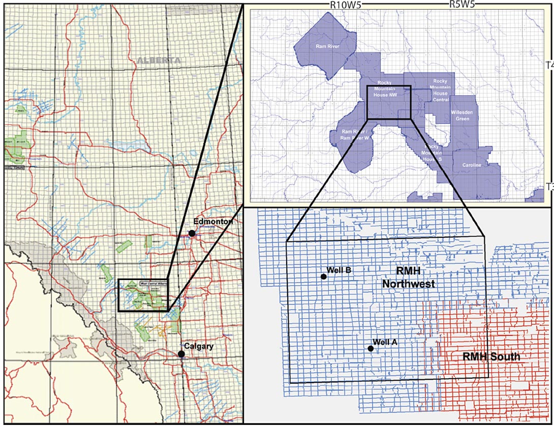
Appropriate well log data are critical in the AVO inversion workflow. Specifically, shear sonic log data are required, in addition to the more commonly acquired compressional sonic and density log data. In this study available well log data from two wells in the area (shown in Figure 1) are used and wavelets are extracted from each of the angle stacks at well A, allowing well B to act as a blind well in which to QC inversion results.
Processing for Prestack Inversion
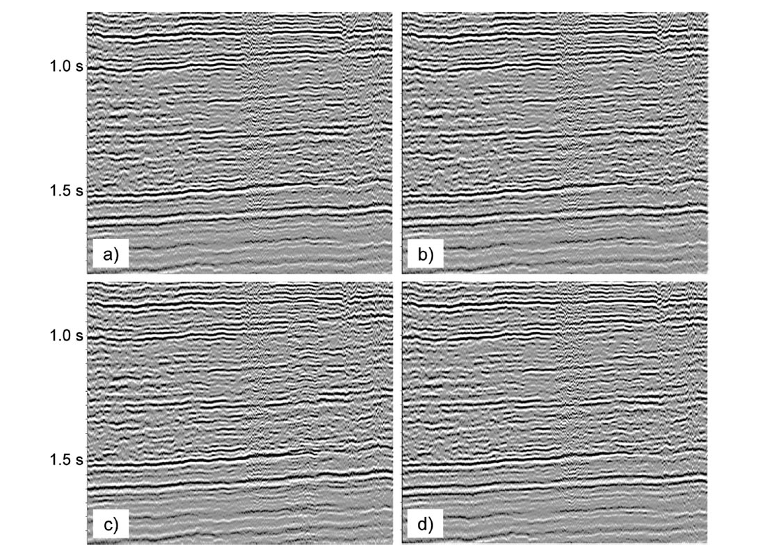
Before looking at the impact of the processes on prestack inversion, what is the impact of SPNA, MBWP, and NRM on the final migrated stack? Figure 2 shows migrated stacks of an inline through both RMH northwest and RMH south with poststack filter and gain. The stack in Figure 2(a) has been through the entire processing sequence and has all processes applied. Each of the other stacks is missing one of the three processes discussed in this study. Figure 2(b) has no SPNA, 2(c) has no MBWP, and 2(d) has no NRM. It is evident from these displays that SPNA and NRM make little difference on the final stack result. The stack without MBWP shows a phase difference and imaging degradation over the merge zone between the two surveys.
Signal Protected Noise Attenuation
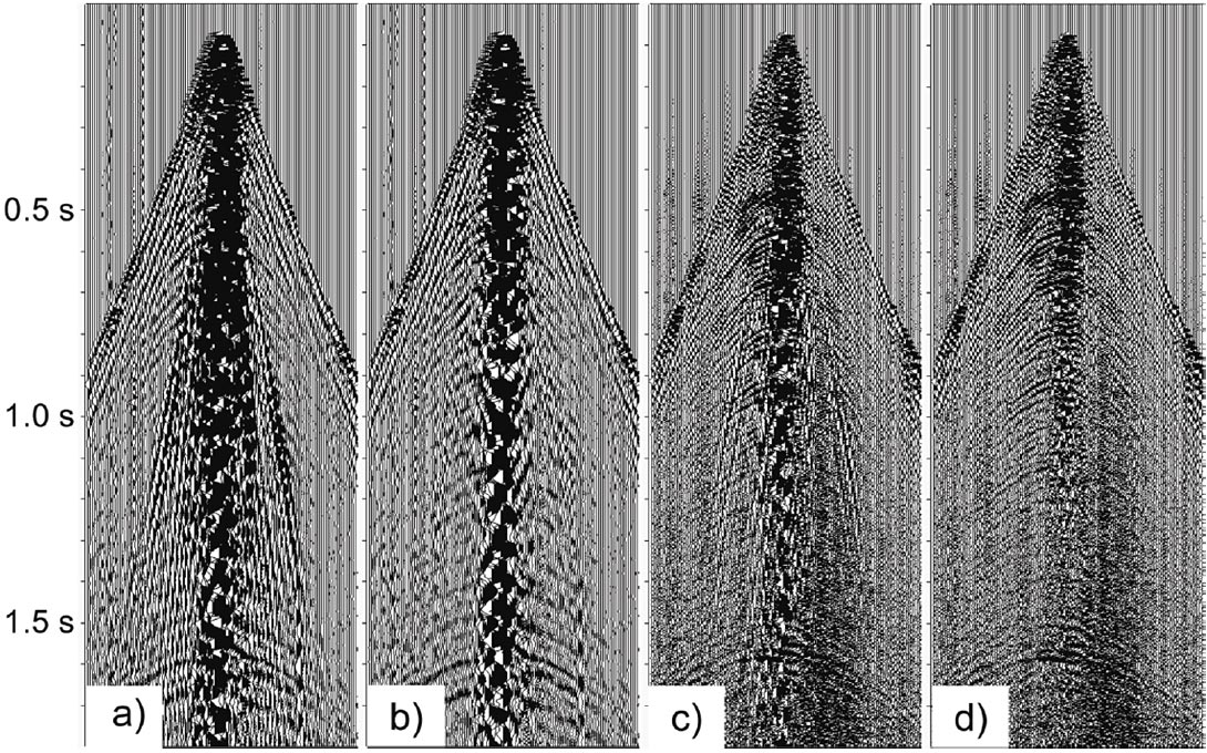
Conventionally acquired seismic data typically do not have the necessary spatial sampling to record surface waves unaliased. This poses a problem in data processing as noise can not be fully removed using an FK or FX based method. If the noise cannot be sufficiently attenuated the migrated data will contain residual low frequency noise on the near offset traces. Figure 3 shows a shot record before (3(a)) and after (3(b)) FX coherent noise suppression. Notice that lower frequency and higher velocity linear noise was removed successfully by the process without damaging the signal. However, there remains significant low velocity energy on the near traces. This is aliased energy and cannot be safely attenuated using a standard FX based approach.
SPNA aims to remove residual noise without adversely affecting primary signal. This is achieved by first generating a noise model and then using techniques to remove any signal that leaked into the noise model. The noise model is generated using more aggressive filters than might otherwise be used meaning that more noise, along with some signal, is removed from the data.
Any energy in the noise model with the properties of the signal is then extracted from the noise model and added back into the data. SPNA is most effective after wavelet and static variations have been accounted for, as the signal is more consistent across the gather. Figure 3(c) shows the shot record after surface consistent deconvolution. Once again, note the low velocity surface wave energy on the near traces. Figure 3(d) shows the shot after SPNA, where it can be observed that a lot the aliased energy is removed and the underlying signal is preserved.
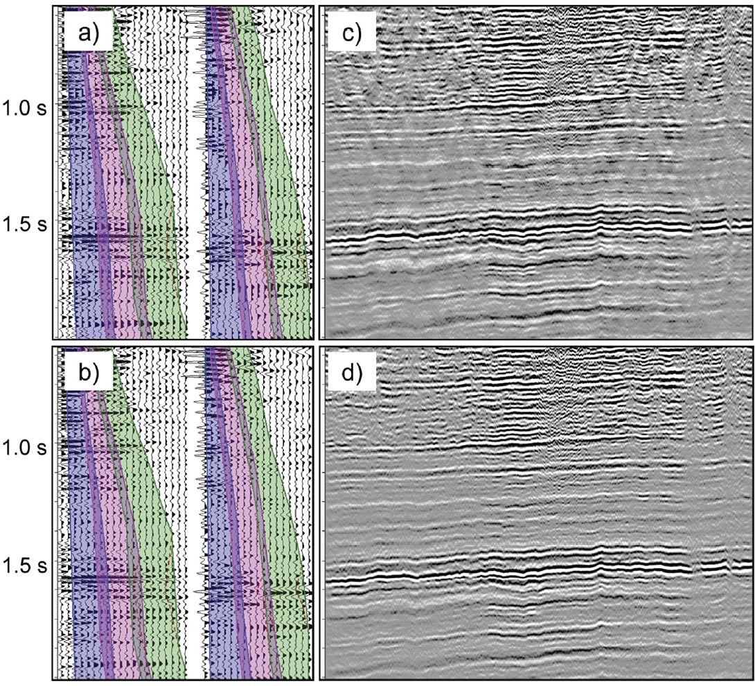
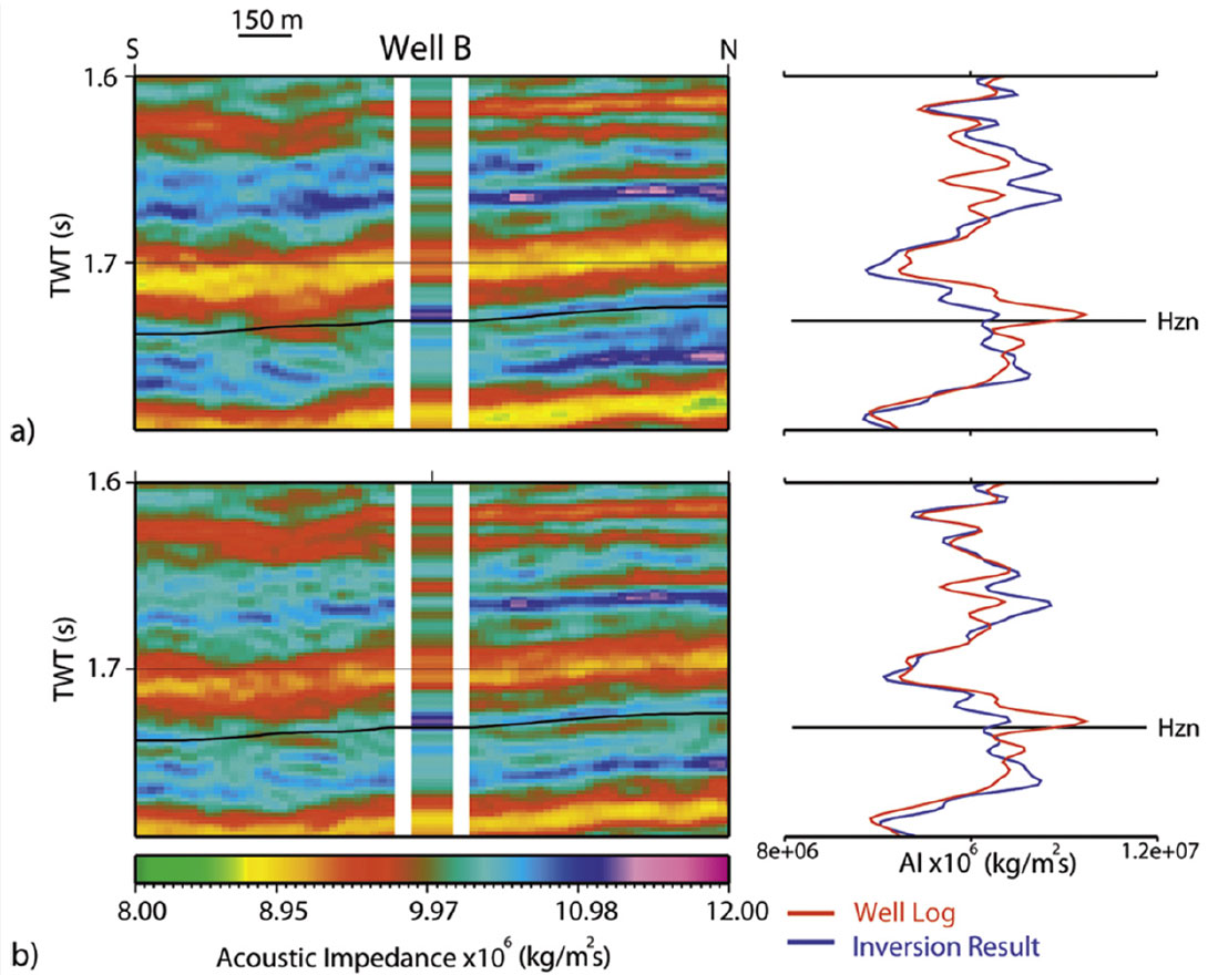
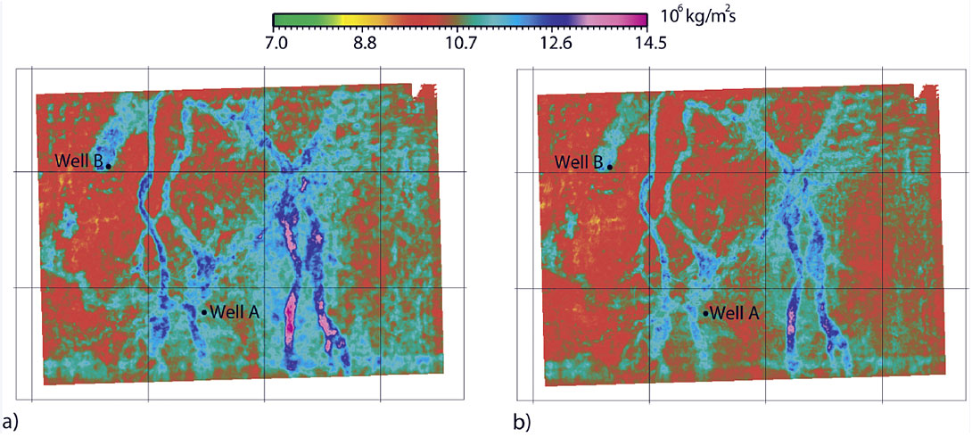
The SPNA has attenuated noise in the shot record, but what benefit does this process have on the inversion result? Figures 4(a) and 4(b) show migrated CMPs with and without SPNA with the angles used for angle stack generation. The data with SPNA applied are cleaner and more continuous on the near offsets, producing a better near angle stack (Figures 4(c) and 4(d)). Figures 5(a) and 5(b) show acoustic impedance inversion results at the blind well B. These figures show a better match between the well and the seismic with the SPNA applied, giving more credibility to the inversion. Figures 6(a) and 6(b) show a horizon slice through the acoustic impedance volume, showing the same main channel features but with different amplitudes. The result without SPNA shows some background noise not evident in the SPNA volume. The noise is higher amplitude in the southeastern section, which corresponds to the amount of aliased surface wave energy observed in the data. These results, when combined with the better well match, give us more confidence in the inversion using SPNA.
Model-Based Wavelet Processing
A primary goal of pre-processing data for prestack inversion is to produce a result with a spatially consistent wavelet. This is typically not too difficult to achieve within a single seismic survey, provided the signal to noise ratio is similar throughout. It becomes more complicated when merging several surveys. Differences in sources, receivers, and instruments, as well as ambient noise levels can lead to wavelet differences between surveys.
Surface consistent deconvolution (SCD) is typically the tool of choice to remove station to station variations introduced by near surface complexities. Provided that the signal-to-noise ratio is fairly consistent, SCD will stabilize the wavelet within a survey. Model-Based Wavelet Processing (MBWP) attempts to remove the wavelet variability between surveys. It takes into account source, receiver, and instrument types, as well as a signal-to-noise estimate to derive an operator to remove any residual amplitude and phase distortions following SCD.
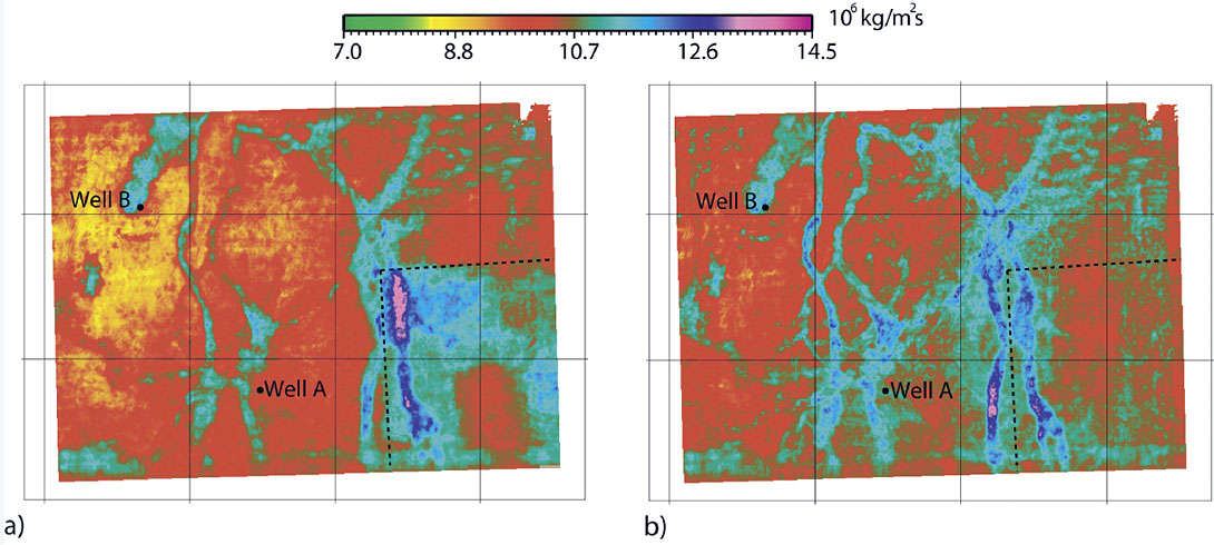
As was shown in Figure 1(c), inconsistent wavelets between surveys will introduce phase distortions across survey boundaries and degrade the seismic image. Figure 6 illustrates the effect of stabilizing the wavelet on the acoustic impedance inversion. It shows the result on a horizon slice over the study area. The sharp change observed in acoustic impedance at the survey boundary in Figure 7(a) is due to unresolved phase and amplitude differences between the RMH northwest and RMH south surveys. Figure 7(b), inverted using data with MBWP, shows a consistent inversion result across the survey boundary.
Residual Gather Flattening
One goal of common offset prestack time migration is to produce flat prestack CMP gathers. However, even optimally processed data typically exhibit some residual moveout due to many factors including inaccuracies in the velocity and anisotropy models, near surface heterogeneity, and shortcomings of the imaging algorithm. Residual moveout impacts the quality of the prestack inversion in two ways. First, the presence of residual moveout causes misalignment of events from near to far offsets, which impacts the stack response within the angle stacks and the alignment of events between angle stacks. Second, residual moveout limits the usable angle range, reducing the range of angles available for input into the inversion algorithm.
Non-rigid matching (NRM) estimates locally varying but smooth time shifts across a seismic gather exhibiting residual moveout. It is computed over a volume in three dimensions, in contrast to other methods that only use individual pairs of traces and hence have no concept of local consistency or smoothness. NRM does not use an external model trace, ensuring preservation of AVO effects, unlike trim statics based methods. It produces a displacement field which can be QC’d and modified before application.
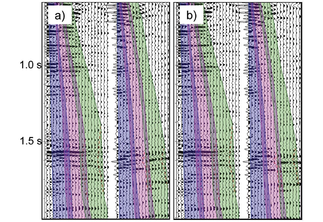
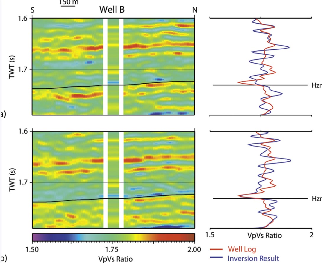
Figure 8 illustrates the effect of NRM on CMP gathers at the two well locations. NRM has successfully minimized residual moveout, better aligning events from near to far offsets. Figures 9 shows Vp/Vs ratio computed at the blind well on data without (a) and with (b) NRM. The misalignment of events on the data without NRM has produced false AVO effects. The data with NRM correlates better with the blind well, increasing confidence in the inversion results.
Inversion Driven Processing
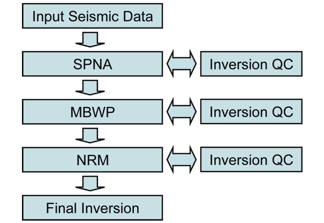
The results shown in this paper demonstrate the sensitivity of prestack inversion results to seismic data processing. If the goal of the data processing is to produce a prestack inversion, the processes should be tailored to give optimal inversion results. This can be attained through close collaboration with the inversion geophysicist as well as inversion QC at several points throughout the processing sequence as illustrated in figure 10. Inversion QC does not replace standard QC on shot and CMP gathers and stacks. However, it can aid in parameter selection for many processing steps. The ultimate goal is to produce the best possible inversion. The earlier on in the processing flow that we start thinking about the inversion, the better we will understand how to process our data for optimal inversion results.
Conclusion
This study demonstrates the importance of careful pre-processing for optimal seismic inversion results. Three challenges that are common to all land datasets were examined. Residual aliased surface wave energy can distort near offsets, impacting the prestack inversion results. This problem can be minimized by using SPNA to remove the noise while preserving the underlying primary energy. Wavelet differences between merged surveys can degrade imaging and inversion results. Using a model-based approach such as MBWP compensates for these differences, providing seamless inversion results across survey boundaries. Finally, residual moveout reduces the stack response within angle stacks and the event alignment between them. NRM corrects for residual moveout to improve the alignment from near to far offsets.
Prestack AVO inversion results are often more sensitive to seismic data processing than traditional poststack products. Close collaboration between the processing and inversion geophysicists is required to ensure quality inversion results.

Acknowledgements
We would like to acknowledge Jennifer Badry of WesternGeco, and David Close and Frederik Horn of Schlumberger for their assistance with this paper. Also, we would like to thank Patty Evens of WesternGeco multiclient for their permission to show data examples from the Rocky Mountain House dataset.
Related Reading


Join the Conversation
Interested in starting, or contributing to a conversation about an article or issue of the RECORDER? Join our CSEG LinkedIn Group.
Share This Article