Summary
The incorporation of faults into reservoir models has often been a fragmented process with different faults being treated in different ways.
Despite the fact that faults can significantly impact fluid flow within the reservoir with the correct fault fluid flow characterization often critical to getting a good history match and despite faults playing an important part in the ultimate recovery and sweep efficiency within the reservoir, a single and integrated fault modeling workflow continues to remain illusive.
Historically, techniques for incorporating faults in reservoir modeling systems have been developed first for extensional systems, and then extended to compressional systems.
This approach has often led to reverse faults (where the hanging wall fault block moves up along a fault surface as a result of compression), and thrust faults being treated as special cases. Manual editing of the model has ensued with the resulting 3D reservoir grids not considered acceptable to reservoir engineers, due to the shape and orientation of the grid cells along the faults.
The methodology introduced in this article will demonstrate how robust structural frameworks and reservoir grids are able to model any type of fault or fault shape, irrespective of how high or low the dip angles are, with no type of fault needing to be viewed as a special case.
This can be achieved through a combination of structural fault modeling, enabling the widest range of fault shapes and intersections to be modeled, including Y faults, lambda faults, K faults, and crossing conjugate or X faults; horizon modeling which provides an easy method for modeling repeat sections due to reverse faults; and reservoir grids created from these frameworks which can treat faults as either pillar or stair-step faults, with stair-step faults often preferred by the reservoir engineer to facilitate flow simulation.
The article will also look at Roxar’s new 3D grid building techniques, which will ensure the building of the best quality grids. Any selection of faults may be treated as pillar or staircased faults. Our methodology used for stair-casing reverse faults also eliminates the shadow zone problems often seen in corner point grids and maintains layer connections across the fault blocks. This is a new technique for structural framework building which will lead to a quicker and more complete characterization of the reservoir and improved models for simulation further down the workflow.
Furthermore, the grid that the engineer needs is also one that the geologist can use for facies and petrophysical modeling. The asset team will also be able to share the model without rebuilding or modifying the basic structure for each discipline, allowing the modeling to be part of a larger workflow and reducing the time required to build a structural framework, thereby freeing up asset team productivity to build more scenarios and reduce uncertainty.
The first step in this article is to briefly examine the importance of the structural framework.
Building the Structural Framework
The structure of a field is a critical component of the reservoir model where you are defining the size, the shape of the subsurface reservoir, and the quantification of the hydrocarbon content.
Get the structural framework for use in reservoir modeling wrong and reserves calculations, production predictions, well placement, and field development planning will all be impacted. Get it right and you might be enjoying one of the most significant productivity enhancement opportunities available in reservoir management today.
The North Sea is a case in point of not having an accurate initial structural framework. Here, reserves have increased or decreased by more than 50% in more than 40% of the fields (The Norwegian Petroleum Directorate, May 2003.). This has led to the requirement to drill 60 to 80% cent more wells than originally anticipated in the field development planning process, directly affecting the financial return of each project.
A greater focus and more effective structural framework can also lead to a much greater return on investment from data acquisition and interpretation expenditure, and increased productivity from one’s workforce. A successful and robust structural model also has productivity ramifications for asset teams further down the line. With geologists able to output simulation friendly grids with all faults incorporated, it will be a lot easier to run the models through the simulator at the later stage.
In addition, delays when producing structural models can also be highly damaging, leading to delays in production, the missing of bid dates, or incomplete models going to simulation.
Building structural frameworks for use in reservoir modeling often consists of three main steps: modeling faults, modeling horizons, and then constructing the reservoir grid. In some methods, the last two steps are combined into a single process.
Existing methods, however, come with limitations at each stage of the process with some stronger in fault modeling, some in horizon modeling, and some in grid building, but to date, none with the ability to tackle the challenge of reverse or thrust faults.
Compressional structures pose problems at all three steps of the process.
First, modeling thrust faults, where the dip of the fault can change from low angle to high angle, can be difficult for pillarbased fault modeling systems, as the number of nodes on the pillar is often limited to a fairly small number. This limits the number of straight-line segments on the pillar and the curved nature of the fault may not be captured correctly.
In addition, low angle intersections between thrust faults may not be correctly modeled, as these low angle intersections can distort the pillar shape.
In the second step of horizon modeling, there is the problem of multi-valued horizon data. Because the horizon exists at two or more different depths at the same XY location, the horizon surface cannot be modeled as a single continuous surface.
One means of avoiding this problem is to go directly to a 3D grid from the fault framework without creating an intermediate horizon model. This solution is not ideal, however, as it requires the modeler to make decisions about grid parameters very early in the modeling process. It also requires a complete rebuilding of the model whenever grid parameters are changed – a cumbersome and time consuming process.
Finally, a 3D corner point grid cannot use stair-step gridding for the thrust faults without either creating problems in the shadow zone areas or losing layering index continuity across the faults.
To meet these challenges, Roxar has developed a new technique for structural framework building which meets the reservoir modeling challenges of compressional structures. We create a horizon model as an intermediate step between the fault model and the grid in order to allow flexibility in grid construction. Our gridding method also allows stair-stepping of the reverse or thrust faults while preserving the layering indices across the faults.
This technique is not just a new method of creating a fault framework, but also applies to the creation of the geologic model and the reservoir grid. The method does not require compromises or simplification in types of faults, numbers of faults, or types of intersections; does not require compromises or simplifications in horizon modeling of complex shapes such as repeat section; and does not require compromises or simplifications in creating the reservoir grid, such as limiting the types of intersections that can be made.
Whereas other methods (pillar methods and binary tree methods, for example) have difficulty in modeling low angle faults, nested Y-faults and self-truncating faults, the new methodology has none of these limitations. Sections of faults are bounded by other faults which cross or touch the fault, and these sections may be manipulated independently of one another.
The Methodology in Detail
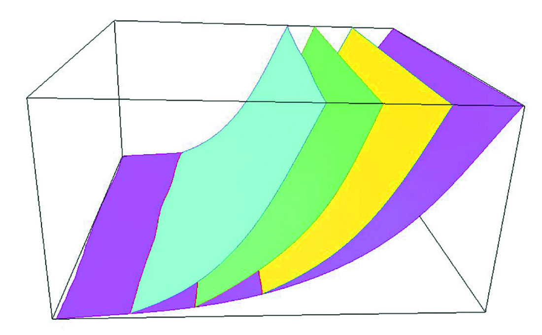
The method that we use to create the faults surfaces (similar to the technique of Zoraster and Bayer, 1993), does not use pillars and produces fault surfaces with correct shapes. Because the fault intersections do not rely on pillars, the low angle intersections between faults are correctly handled (Figure 1). This is as opposed to pillar fault modeling methods, where due to the number of nodes on a pillar often being limited to a small number, the curved nature of the faults and the low angle intersections can pose problems, as previously mentioned.
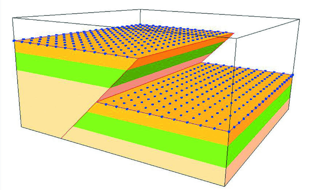
The horizon modeling method uses a fault block-based approach. That is, the fault framework is used to sort the input data by fault block. A horizon surface is generated for each fault block and these surfaces are intersected with the fault framework to create the full, solid model.
This type of approach means that all data in the shadow zone of the fault can be used correctly (Figure 2). The primary advantage of creating a solid model first, as opposed to going directly to a grid from the fault framework, is that decisions about grid increment and layering and fault treatment do not have to be made early in the modeling workflow.
Instead, one solid model can be used to create many grids, allowing both the geologist and the engineer to create a fit-forpurpose grid from the same structural framework.
With high angle, planar faults, the faults can be treated as pillars in the grid with little problem. However, with faults with lower angle, the cells near the fault become less and less orthogonal; in some situations, this can create problems for flow simulation as the k edges of the cells are no longer close to vertical.
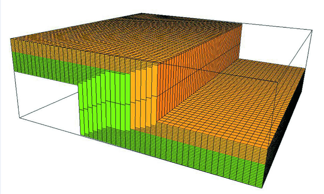
The engineer may require cells with vertical edges, which means treating the fault as a stair-stepped fault. However, this poses problems similar to those encountered in horizon modeling where there are cells with the same ijk index at different depths. In this case, only one cell is created, which spans the depth from the first to the second occurrence, creating a very thick cell in the shadow zone (Figure 3). This type of grid is useless for property modeling or for simulation.
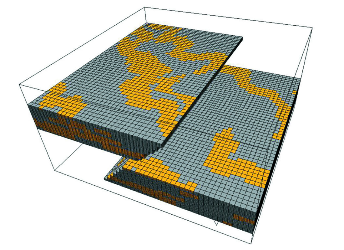
A fault block-based solution can be used, but only with a special variation. If separate grids are created in each fault block, they will have their own ijk indices, and will not have any connection across the fault. We have developed a technique of stair-stepping the reverse faults (Figure 4) and re-indexing the cells to preserve the layering indices across the fault.
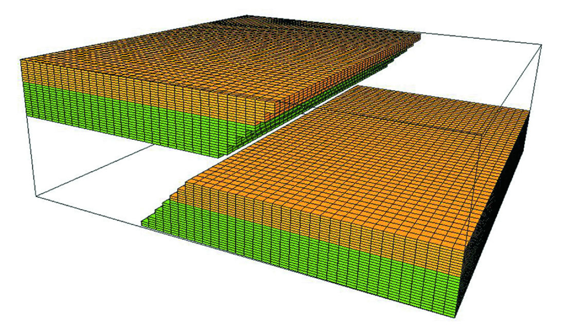
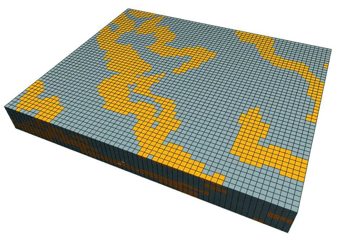
Property modeling done carried out using this grid will thus have continuous properties from fault block to fault block. A simple example of channel facies modeling using this grid shows that the channels are continuous across the fault (Figure 5). When the grid is displayed in modeling space – the grid layers are flattened – the fault is essentially removed from the model and the continuity of the channel objects is clearly shown (Figure 6).
Models with Complex Geometries
The advantages of using this approach are demonstrated by models with more complex fault geometries – a schematic fault bend fold model, for example. This model contains a single fault, and is a simple-ramp fault bend fold of the type described by Suppe (1983). This model assumes constant layer thickness and no deposition or erosion on the depositional crest of the fold.
Although this model is simple in terms of the number of faults, the shape and orientation of the fault precludes treating it as a pillar fault either in the structural framework or the 3D grid. The fault is particularly difficult to model, as it has two horizontal sections joined by a dipping section.
Treating this fault as a pillar fault in the fault modeling process might be possible when the fault pillars are allowed to have multiple nodes on the fault. However, in the 3D grid, the fault is usually constrained to a single straight line segment. If the grid is constructed for the entire model, then the fault would be a straight line from the upper left to the lower right of the model. The approximation of the pillar to the actual fault would therefore change the structure significantly.
The resulting model would have incorrect volumes, and could not be used for any realistic well placement. Existing wells could easily be placed in the wrong fault blocks, which would mean that any property modeling would be incorrect as well. The well information would also be in the wrong fault block and also the wrong reservoir layer.
When the fault is treated as a stair-step fault instead, the shape of the fault and the shape of the structural layers are correctly preserved. This of course means that the location of any existing wells would be in the correct fault block and reservoir layer not only in the structural framework but also in the 3D grid. Even in a model, such as this, where the shadow zone of the fault covers most of the model area, the k layering indices are maintained throughout the grid. Property modeling using this grid would thus distribute property values in the correct fault blocks and layers.
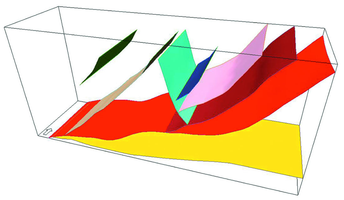
A more complex model, with several faults, is shown in Figure 7. This model is a faulted anticlinal structure, with fault zones along the backlimb of the anticline (after Florez-Niño et al., 2005). Many of the faults are at a high angle to the axis of the anticline. The main thrust fault in this model has a curved, undulating shape which would be extremely difficult or impossible to model in a pillar-based system. The limit of the number of nodes that may be used for a fault pillar is often too low to be able to accommodate the number of inflection points in a fault surface such as this.
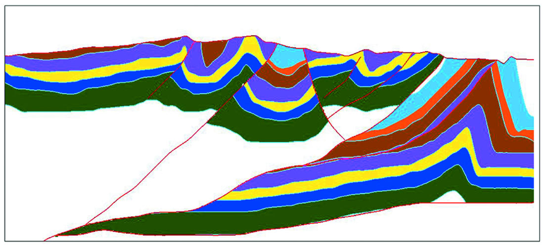
The number of faults in this model, while relatively few, create several areas of repeat section, including some with multiple repeats. As with the simple fault bend fold model, the approximation of fault shapes as pillars in the reservoir grid would not preserve the actual structure in the 3D grid. Treating all faults as stair-step faults (Figure 8) does preserve the structure and allows the use of this grid in further modeling.
Conclusions
Current methodologies have limitations to the types of fault intersections, and the number of faults that realistically can be modeled. The structural framework is often a compromise between the actual structure and what the modeling system allows, particularly in areas with large numbers of Y-intersections, low angle faults, or reverse faults.
Roxar’s method of creating structural frameworks and reservoir grids, however, can model any type of fault or fault shape including faults from compressional structures. Faults with multiple inflection points or faults that change dip angle from low to high are not a problem, as the shape of the fault is not constrained by fault pillars or nodes. Low angle intersections between faults can also be modeled correctly as these intersections do not distort the shape of the fault surfaces.
Faults may be represented as pillar faults or stairstepped faults in the reservoir grid. Stair-stepping the faults honors the shape of thrust faults better than treating these faults as pillars, and thus creates an accurate structural model. Wells are placed in the correct fault blocks, and property modeling is therefore correct.
We have also solved the problem of preserving the k layer indices across the stairstepped reverse faults. The shadow zone is not filled with unusable cells, and the layer connection between the fault blocks is maintained.
Furthermore, the technique of using a fault-block based approach to horizon modeling also utilizes all horizon input data, even in the shadow zone of a reserve fault. The creation of this model prior to creating the 3D reservoir grid allows the modeler to concentrate on creating an accurate structural framework prior to making decisions about the grid parameters.
And the benefits for asset teams and operators?
With the structural framework used to create multiple grids, such as geologic scale and engineering scale grids, which are consistent with each other, the accuracy and the speed of building structural frameworks is improved.
It is now possible not only to create fault frameworks of complex truncations and compressional structures but also to take these frameworks through to reservoir gridding without having to simplify or alter the fault relationships. The geologic structure does not have to be compromised or simplified in order to fit the constraints of the modeling systems.
The interactivity and integration of the model-building process (as opposed to different faults being treated in different ways) also allows an asset team to test a variety of interpretations where appropriate, or to include the details necessary to make informed reservoir management and production optimization decisions.
In addition, the simplicity of building and editing the fault relationships, creating the stratigraphic model, and building the reservoir grid means that all members of the asset team can easily update a model, test different interpretations, and use the model for both geologic and engineering applications. At a time when there are growing staff shortages and a need to increase productivity, this is incredibly valuable.
The result is a model for the asset team that is usable for many applications, such as volume calculations, well placement, property modeling, and simulation. The workflow of building this model can also be incorporated into a larger workflow that explores the uncertainty associated with other modeling steps.
The end result will be quicker and more accurate characterizations of the reservoir, better decision-making, and maximum reservoir performance.

Acknowledgements
The author would like to acknowledge the contributions of all members of the development team, including John Neave, Erik Nilsen, Tor Barkve, Stein Gulbrandsen, Mike Zerzan, Martin Sovik and Sarah Vitel, to this work.
Related Reading


Join the Conversation
Interested in starting, or contributing to a conversation about an article or issue of the RECORDER? Join our CSEG LinkedIn Group.
Share This Article