The development of shale and tight sand resource plays over the past decade has dramatically changed the oil and gas industry. Advances in hydraulic fracturing technologies have unlocked vast unconventional hydrocarbon resources. Unfortunately, the vast supply (together with other external factors) has led to a price collapse that has plunged the industry into a depression. We’ve seen producer revenues shrink while expenses remained high, pushing balance sheets into the red. The typical corrections have been applied to reduce costs: projects have been delayed, investment stalled, and headcounts reduced. The impact of widespread revenue reduction has also been felt throughout the supporting businesses. In the early 1980s, the downturn in industry was referred to by some as “The big crew change”. The loss of experienced staff was associated with a major age, training and knowledge gap. Schlumberger’s 2011 HR assessment report suggests it can take as many as 11 years to acquire the necessary skills to make nonstandard, original technical decisions when working for national and international oil companies (Bertrand 2015). The current low price environment is shaping another big crew change, and we could be facing another decade-long knowledge gap. It’s more important than ever that we document our approaches, technical successes and challenges, and reduce the impact of the loss of staff, training and knowledge.
A key technology that has been widely used for unconventional resource development is microseismic monitoring. The information derived from microseismic monitoring has the potential to characterize and image the induced and natural fractures enhanced by the hydraulic fracturing injection process. The microseismic event datasets can be used to provide feedback on the quality of the drilling and completion design, stimulation design, and the geologic and geomechanical factors that impact the stimulated fracture network (Maxwell, 2014). It is one of the few tools used to evaluate completion effectiveness and the stimulated reservoir/rock volume that has been shown to be effective in explaining production variations (Iverson et al., 2013). Microseismic monitoring technology has expanded and evolved over the past decade. Interpretation has evolved from basic visual assessment to a complete decomposition of the signal, with supporting principles based on the physical processes. Wide collaboration and strategic investment have led to major learning and improvements in microseismic monitoring, and in turn have helped to optimize the development of shale and tight sand resources. This article references some of the publications that highlight the learning and improvements in microseismic monitoring that have been established through collaborative efforts driven by teams of geophysicists, service providers, geologists, geomechanics specialists, and completion and reservoir engineers for projects carried out in the Horn River Basin for Nexen from 2010-2015.
In this paper we will highlight the unique geophysical approaches applied to shale resource development. We detail the long term investment strategy in the technology, and new approaches to analyse and understand the observations. These original approaches have led to many successes, challenges and new insights into the dynamic nature of hydraulic fracturing.
Nexen first used microseismic event locations for reservoir and completion evaluation. The challenge was to extract additional information from microseismic signals and go beyond microseismic event locations in relation to hydraulic fracturing. A long term investment strategy in the technology and new approaches were developed to analyze and understand the observations. We will follow up this document with a subsequent publication discussing the new ideas generated and some of the insights into the physical processes of the hydraulic fracturing as related to the microseismicity.
Geological Setting
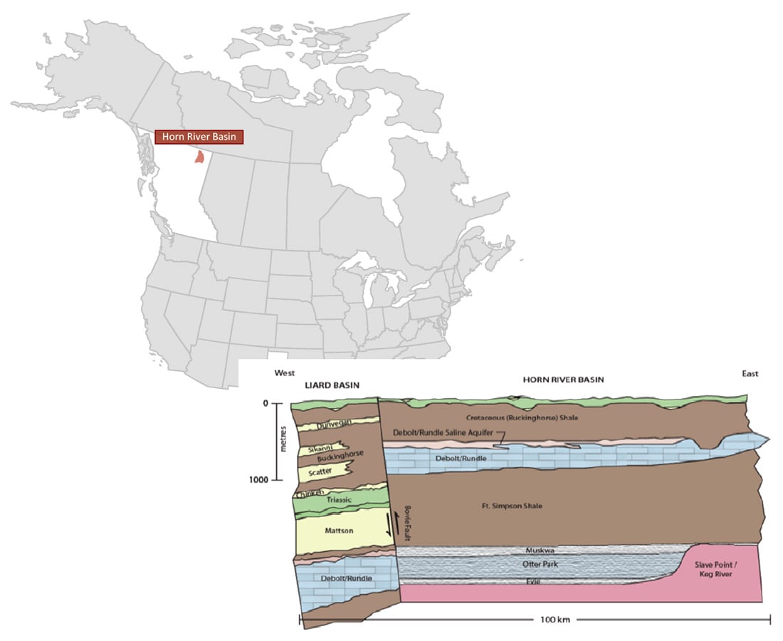
The area of interest for this paper was the Nexen shale gas project in the Horn River Basin. It is situated in northeast British Columbia, as shown in Figure 1. The basin is bound to the west by the Bovie fault structure, and to the east by the Slave Point (Keg River barrier reef) carbonate platform. The target zones are the mid-late Devonian shales of the Muskwa, Otter Park, and Evie Lake. The depth to target at Nexen’s lease blocks is 2400 m to 2600 m. Regional 2D seismic lines indicate that there are multiple major faults with orientations (N-S and NW-SE) that suggest a complex tectonic history. The present regional maximum horizontal stress is oriented NE-SW. The targeted shales are grouped into two reservoir packages, the Muskwa-Otter Park and Evie Lake. Extensive core and well log characterization and well tests reveal that both reservoir packages are overpressured. They are separated by a lower Otter Park claystone. The top of the Muskwa- Otter Park reservoir is bound by the Ft. Simpson shale, which is a clay-rich, TOC lean, low effective porosity and low permeability zone. The Muskwa is a highly fractured siliceous mudstone interbedded with organic-rich laminated mudstones. The Otter Park is a siliceous calcareous mudstone with a variable degree of lamination and different fracture properties than the Muskwa. The variability of fractures seems to be due to the variation in lithofacies. In turn the variation in fracture properties has a strong influence on the observed stimulation geometries. The Evie is an organic-rich calcareous, siliceous shale, which unconformably overlies the Lower Keg River carbonate unit. The upper zone of the Lower Keg River carbonate is a clean carbonate with very low porosity and permeability, which is an effective barrier that contains the hydraulic fractures within the reservoir. Below the upper zone, the Lower Keg River is dolomitized, creating additional porosity.
Monitoring Objectives and Initial Workflow
The initial objective of Nexen’s microseismic monitoring projects was to track the performance of the hydraulic fracture completions of multistage, multi-well pads. The desired effect of the treatment was to maximize the fracture network in order to maximize the gas that would return to the wellbore during flowback of the well. Observations of geometric patterns generated by the hydraulic fracture stimulation were made and used to examine production variability, well design and completions parameters. The parameters that were analyzed include: variability of production, the effect of orienting horizontal wells in a certain azimuth, well placement, water volume per stage, changes in perforation style, zipper frac order, proppant sand type and volume, stages without plug separation, cased uncemented wells, and longer lateral well lengths.
Completion and drilling technology evolved and enabled faster drilling, faster completion times, and many optimizations that led to tremendous efficiencies in the hydraulic fracturing process. Optimizations were made to the drilling and completion techniques and subsequent microseismic monitoring helped to validate the changes. Beyond event locations, enhanced microseismic data analysis was integrated with completion data, production data, geomechanical modeling, and 3D seismic data and attributes. Based on the results of the different tests performed, updates and optimizations would be made to the well and completion designs.
The well design cycle continued as new design tests were posed for the following well pads over the next 5 years. After each pad was completed, the monitoring results were reviewed to examine completion effectiveness. An early application of using basic geometric analysis of microseismic data was to evaluate the plugless stimulation method (Chernik et al., 2014). The concept of effective hydraulic fracturing without plug isolation between stages was confirmed by minimal microseismic stage overlap. Early successes in monitoring solidified microseismic as a useful tool for subsequent testing at future well pad locations.
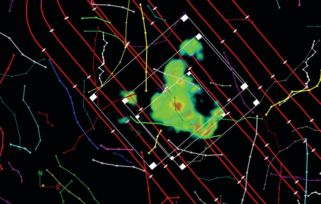
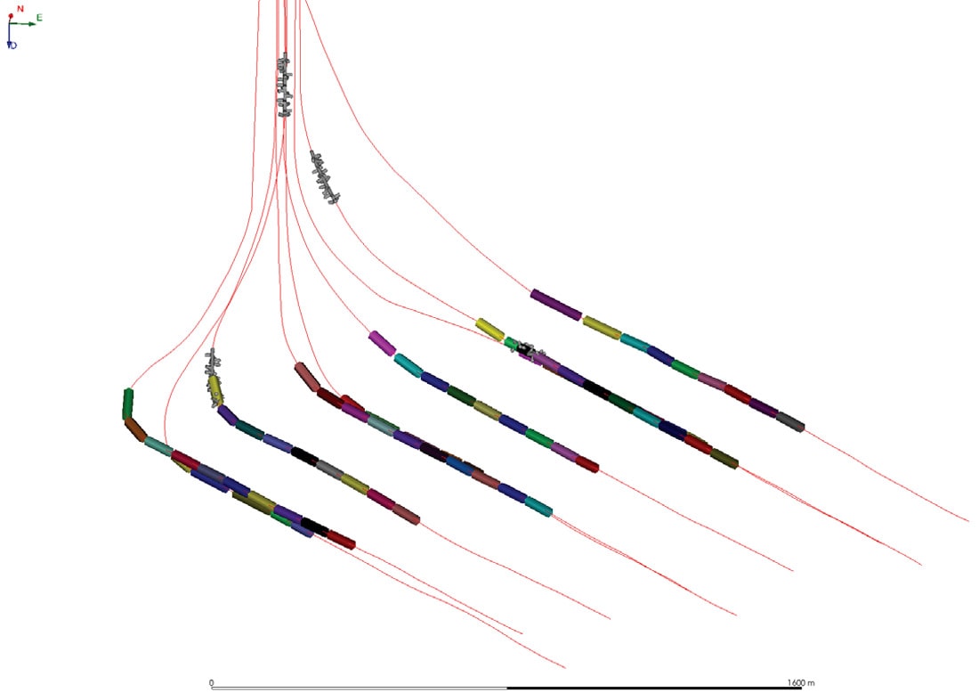
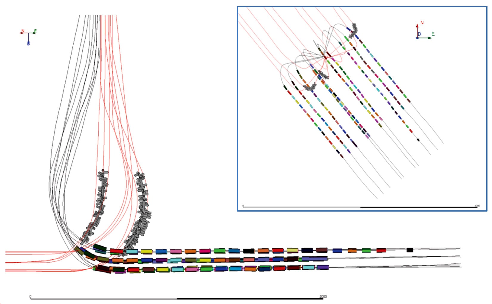
Microseismic event locations generally aligned along the regional trend of expected maximum horizontal stress, however the event clusters revealed a much more complex response than expected. Wider, complex, overlapping fracture zones were imaged and very few stages had linear microseismic clusters. Stage to stage, different geometries were observed. Some stages had asymmetric event distributions, some had event clusters that were large and some that were small. In some areas, unpredicted downward growth of events into the Lower Keg River carbonate occurred along planar trends, as shown in Figure 2. These stage geometries appeared to be controlled by faults. Some stages appeared to be compartmentalized, controlled by mapped lineaments, as shown in Figure 3. Beyond geometric analysis, complexities in the microseismic response needed to be quantified. These results suggested that the variables controlling the stimulation and microseismic emissions were not well understood. These complexities led to many new questions about the effect of faulting, reservoir properties and geomechanics. Do the microseismic events represent a connected fracture network? How do we define the stimulated reservoir volume? Were our results consistent with other operators in the area?

Projects were initiated to examine the fracture mechanism, complexity, intensity, connectivity, and efficiency, likely fluid flow paths, and parameters, such as fracability, diffusivity, and the dynamic rupture process of microseismic events and their source complexity (Urbancic et al., 2016). Significant investment was made to further the use of this technology, from acquisition and processing to interpretation.
Innovations through Investment
Towards the late 2000s, successes in microseismic monitoring were becoming more common. Complex fracture mapping in the Barnett Shale led to new insights into hydraulic fracturing. As an example, Nexen first used microseismic monitoring in 2008 in the Horn River Basin, with some positive correlations between complexity and stimulation effectiveness. However microseismic monitoring was viewed as an immature technology. There was not a standard list of deliverables, acquisition design was restricted by the service providers, and quality control was difficult. In order for microseismic monitoring to be considered a reliable technology, many improvements had to be made. Being able to confidently provide datasets that could help isolate the variables that were affecting the completion effectiveness and well productivity, was targeted as a goal. Recognizing the potential of microseismic monitoring from Nexen’s early results and from successes in other shale basins, new questions were posed:
- What resources can be leveraged to improve the application of microseismic information?
- What improvements to the data acquisition can be made to improve the data quantity and quality?
- What improvements to the data processing workflow can be made to improve the data quality?
Below is a summary of the learning on how these technological advancements were applied in terms of interpreting microseismicity as the geomechanical response of the reservoir. We will address how we leveraged all of these resources and advancements in acquisition and processing in a subsequent publication.
A. What resources can be leveraged to improve the application of microseismic information?
Microseismic monitoring has been applied in different forms since the 1970s for monitoring industrial activities such as mining and fluid injection. Acquisition programs in Cotton Valley (Urbancic et al., 2000) demonstrated the commercial viability of the technology for hydraulic fracture imaging. Concepts such as the state of stress, pressure, fault slip, and failure mechanisms emerged. There were also early data integration efforts with numerical modeling, and pressure and production comparisons published on the Cotton Valley and Barnett Shale formations (Mayerhofer et al., 2006). However, quality standards were not yet established, academic research groups that were focused on microseismic monitoring were difficult to find, and the complex nature of the data was difficult to interpret. In order to use microseismic data as a reliable technology, there was a need to improve all aspects of the microseismic workflow. Operators like Nexen were committed to this challenge, through long-term and broad investment into advancing microseismic technology. However, it was evident that partnerships were needed to tackle these areas simultaneously.
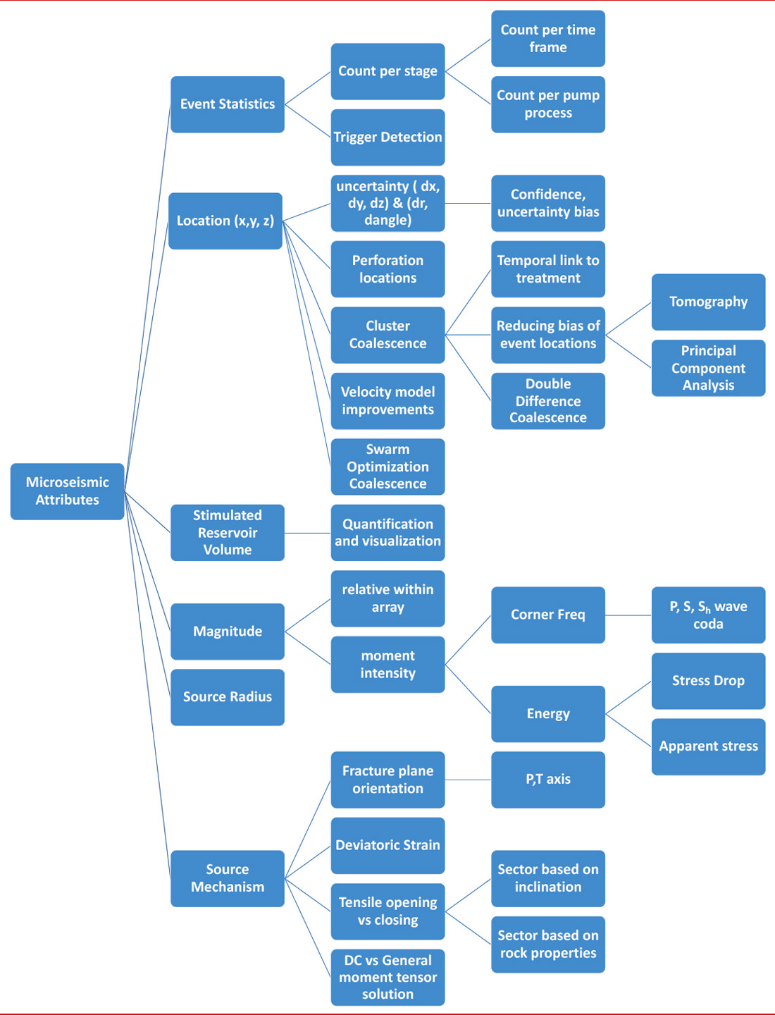
Industrial and academic partnerships in data acquisition, data processing, data analysis, and software development were established. Joint research avenues were established in order to try new approaches, share project risk, and provide reasonable validation of the results. Figure 4 highlights the attributes that were investigated and developed to try to achieve the questions posed above. As new theories were formed, additional research project scopes were created to examine them, and appropriate resources were allocated. Working with an industrial software consortium, companies like Nexen sought to develop better software tools for the interpreter, resulting in the development of an event location quality control toolkit, where users can compare and validate the positions of microseismic events. Working groups and academic consortia were also formed to investigate and research anomalous induced seismicity. We proactively worked to understand this issue by installing one of the first monitoring networks specifically designed to monitor for induced seismicity from hydraulic fracturing, supporting academic and government research, and producing one of the first operational protocols to address induced seismicity.
B. What improvements in data acquisition can be made to improve the microseismic data quantity and quality?
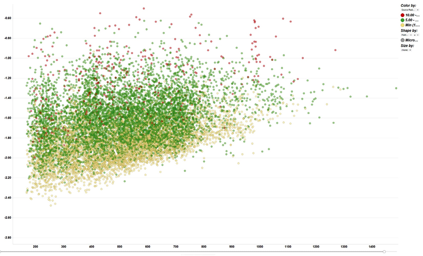
Nexen’s multi-well surface pads were leveraged to access multiple downhole observation arrays using idle wells. The strategy was to obtain accurate event locations and accurate characterizations of hydraulic fracturing. From the early monitoring programs, it was noted that the highest quality and quantity of microseismic data were found proximal to the monitoring arrays. The detectability was observed to be highest and, as shown in Figure 5, small events were attenuated as they were located further from the array. As the distance to the monitoring array increased, the location error also increased and fewer events were reliably located.
Different array technologies were tested and implemented, including the ‘whip’ array. This type of array, shown in Figure 6, enabled two arrays on one wireline cable. To improve the monitoring of the stages near the well toes, horizontal arrays were installed up to 1.5 km into the horizontal section of the well. A wellbore tractor was experimentally used to pull the wireline array along the horizontal section of a monitoring well. The high amount of vertical uncertainty on events detected on the horizontal array is reduced when used in combination with a vertical array. Improvement in acquisition recording systems enabled longer monitoring arrays to be assembled. By 2013, 48 geophones per monitoring array were deployed on a single array. This enabled a significant increase in the detectability of events, and some wells averaged over 2,000 located events per stage. Multi-well recording from offset positions allowed for tighter constraints on the locations of the events, better head/direct wave separation, and the added sampling of the P and S wave radiation patterns allowed for robust determination of moment tensors. The moment tensors have been shown to reveal fracture orientations, the stress and strain state of the reservoir during injection, the response of the mechanisms during treatment, and a wealth of other data (Baig and Urbancic, 2010).
A dedicated Nexen field team was put in place for the duration of the monitoring program. On site Nexen geophysicists collaborated with the acquisition service provider. The field team coordinated the acquisition with completion engineers and the well pad supervisor. The raw data was processed in the field by a team of data processors and returned immediately for review by the interpreting geophysicist. Feedback was communicated with the asset team about the results of the monitoring. Real time decisions could be made to optimize the monitoring system. The 2010 monitoring program was successful in monitoring 143 out of 144 frac stages.
The completion program that was monitored in 2013 featured a new and unique layout of wells trajectories, which coincidentally improved the monitoring geometry. Figure 7 shows the wells in one half of the pad were interlaced with the wells in the other half of the pad in an effort to minimize bypassed reservoir regions. There were 10 wells available to monitor the 10 wells that were being completed. Therefore, unlike the previous monitoring efforts, arrays were able to be placed in close proximity to the injections without needing to swap arrays in and out of different active completion wells. This alleviated the on-site logistics and coordination with the frac crews, minimized the resonances observed on the instruments and allowed for fewer complications in characterizing the frequency response of the seismicity.
With the multi-array geometries that were applied to the locations of these data, the determination of moment tensors was readily facilitated. The moment tensor is a matrix of nine force couples that are used to describe the source mechanism (Aki and Richards, 2002). Once a moment tensor solution is determined, it can be decomposed into the source mechanisms. The components are typically displayed on a source type graphical plot introduced by Hudson et al. (1989). Baig and Urbancic (2010) provide an overview of moment tensor inversion and how it applies to understanding hydraulic fracture growth. The mechanism of rock failure, stress-strain changes, slip direction, in-situ geomechanical properties, and likely fluid flow pathways can be determined using seismic moment tensor inversion (Wuestefeld et al., 2013). Multiple borehole arrays placed around the stimulation can provide reasonable sampling of the focal sphere in order to reliably estimate the moment tensor (Hendrick et al., 2012). For the most recent 10 well pad, over 30,000 moment tensor solutions were generated. The wealth of these data allows for robust constraints to be placed on the discrete fracture networks, as well as investigations into the variations in the stress state through the injections (Baig et al., 2015).
At the time, hydraulic fracturing in the Horn River Basin was observed to be more actively seismogenic than many other shale basins (BC Oil and Gas Commission, 2012). Downhole and surface microseismic monitoring is usually accomplished through the use of high frequency (10 or 15 Hz) geophones that saturate and do not capture the low-frequencies necessary to characterize larger events. Improper monitoring can result in underestimation of the radiated energy of the seismicity (Baig and Urbancic, 2014). In order to overcome this saturation bias, we deployed a near-surface network of 4.5 Hz geophones and force balance accelerometers to characterize this seismicity. This allowed for precise location of large magnitude events to be determined unambiguously when combined with the downhole data stream. The accurate spectra characterized the larger magnitude events (~>Mw 0), in terms of their magnitude and the dimensions of their associated ruptures. In their first year of deployment, the near surface network registered nearly 800 events with magnitudes ranging from below Mw 1.0 up to Mw 2.9. During the following pad completions program, only 19 events (Mw 0.2 to Mw 1.1) were located. This emphasized the local geological variations controlling induced seismicity from hydraulic fracturing.
Predicting the impact of faults can be a major challenge. There is a predictable relationship between observed faults and sub seismic fault through a single power law relationship (Walsh and Watterson, 1988), and the stress conditions that explain the behavior of faults are well documented in Zoback, 2010; however, identifying discrete faults that potentially pose a hazard remains a challenge.
C. What improvements to the data processing workflow can be made to improve the data quality?
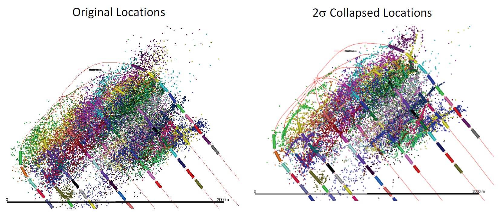
Along with improvements in data acquisition, many considerations in the processing workflow were addressed. A considerable amount of effort was put into reducing the uncertainty in event locations. The efforts included the research and analysis of attenuation, vertical resolution, boundary effects, and event cloud collapsing and clustering.
A detailed study into the effect of attenuation on the source parameters was undertaken. When determining the corner frequency of the source displacement spectra, there is a strong effect of attenuation that must be considered. The benefit of having numerous geophones recording events at different offsets enabled the Qp and Qs to be calculated at each sensor. Viegas et al., 2013 showed that attenuation can bias the calculated source parameters and physical properties. The local velocity model for each monitoring project was iterated numerous times beyond the initial model. The initial models that were used to process the first microseismic datasets were derived from sonic logs and were suspected of oversimplification. Experiments in velocity model construction using different sources were conducted. In addition to sonic well logs to build the geological model, vertical seismic profiles, particle swarm optimization (PSO) and seismic tomography were used to improve event locations (Karimi et al., 2013). More information was input about the velocity anisotropies, lateral heterogeneities, and from calibration points obtained throughout the frac programs. Because of the highly anisotropic nature of the shales and fracture systems in the reservoir, boundary effects caused microseismic events to collect along modelled velocity model interfaces. The combined effect of the monitoring geometries caused direct and head waves to be detected for a single event. The downhole array placement was often bed-parallel and/or slightly above the reservoir. The horizontal velocities were complex, and anisotropic heterogeneities were introduced into the horizontally transverse isotropy (HTI), likely due to fracture sets and the differential horizontal stresses (Grechka and Duchkov, 2011). Location error could be reduced by applying post processing algorithms such as collapsing and clustering, as shown in Figure 8, as explained by Wuestefeld et al. (2013). Other methods included applying tapered velocities in the velocity model and double difference relocations to improve event locations. In order to better understand the complexities in velocity anisotropy, a series of pseudo-vertical seismic profiles (VSP) were generated near the well pad. Although the microseismic monitoring arrays had a limited number of geophones, they could be used for VSP acquisition. A compressional wave vibrator truck was used at different source location on surface. Vibrator source positions were selected near the well pad, at a range of zero offset, walkaway offset, and azimuthal offset positions. Each of these generated velocity profiles in different planes to the receiver array. The VSPs were repeated at regular intervals during the completion program in an attempt to observe velocity changes, time and wavelet character distortion induced by the hydraulic fracture program. With new knowledge about the effects of anisotropy, lateral heterogeneities, and log-measured velocities, better initial velocity models were created.
Post-data acquisition, refinements to the velocity model were made as new calibration points were acquired. The primary source of velocity model calibration was the perforation gun. This source is well known in the microseismic industry to derive velocity models during acquisition and post-processing. The casing perforation system was used as a seismic source point at a (relatively) known point in space. In order to determine the time-zero of the seismic source, a perforation timing system was developed with assistance of the perforation provider. The electrical signal was intercepted as it was sent to the perforation gun, and sent through to an auxiliary channel in the microseismic recording system. With a correction for the wireline length and charge burn time, the time-zero of the perforation shot (known x,y,z position) could be used to estimate the velocity field between the perforation shot and the geophones. This procedure was repeated for each perforation shot to improve the velocity model using different perforation locations along the wellbores. Often the workflow is such that individual perforation shots are used to tune “local” velocity models that accurately locate perforations (and, by inference, events) associated with certain stages. In real-time, we derived VTI models based on the daily records of the perforation shots. Selections of perforation shots recorded were used in a global inversion for a VTI model. This had the advantage of providing a global velocity model that was used for reference and inherently accounted for some of the non-uniqueness that can be responsible for differences observed in the velocity models from these more local inversions. These improvements led to dramatic reductions in horizontal and vertical location uncertainties.
As noted above, the increased volume of raw microseismic data meant that the P and S arrival picking was limited by the human capacity to pick and locate events manually. Due to the increased detectability from the improved arrays, massive volumes of raw data were generated. By developing automatic picking and location algorithms with appropriate QC workflows, the amount of data that could be analyzed was significantly increased. The implementation of automatic picking and location algorithms shifted the processing burdens from picking to inspection, allowing for more events to be located in real time to the same degree of robustness. Continuing improvements in the automatic processing allowed for more robust initial locations, further optimizing human processing time for interpretation and quality control. Furthermore, the removal on the human picker allowed for a higher level of consistency in the final dataset.
In order to ensure there were consistent industry standard deliverables from downhole microseismic acquisition and processing, senior Nexen geophysicists helped to write the CSEG Guidelines for Standard Deliverables from Microseismic Monitoring of Hydraulic Fracturing (Maxwell et el. 2012). These guidelines are meant to capture the vital information during acquisition to process the data, and save the processed data, and any advanced processing data and information for the interpretation of hydraulic fracture growth.
Conclusions
This paper highlighted some of the nonstandard approaches that were undertaken to understand the complexities of the microseismic response of hydraulic fracture treatments. Addressing complex technical challenges in unconventional resource development require planning, thinking beyond the conventional approach, and a long-term strategy of investment and resources. Challenging the capabilities of an immature technology at the right time led to insights and worked toward establishing a reliable technology. Investment and effort was required for all aspects of technology, from acquisition and processing to interpretation and analysis. Collaboration was successful through partnerships with service providers, making use of consortium research and students, and employing in-house students, interns and geophysicists. The integrated discipline asset and design teams were key to the success of these projects, as the asset team was invested in the results of the research. The difficulties lie in isolating variables when testing, and this was a tremendously complex problem. It was necessary to find partners that were willing to take risks and try new technologies and new approaches to abstract problems. In this difficult environment, learning and strategies must be continued and documented. There is a major risk that the knowledge of a generation of geophysicists will be lost, similar to what occurred during the “big crew change” of the 1980’s. It is encouraged that geophysicists ensure that their innovative approaches to technical problems are well documented. It would be wise for companies to continue investing in training, people, data management, and new technologies, in order to reduce the long-term impacts of the industry downturn. It is the responsibility of the technical staff to show the value of this investment to management.

Acknowledgements
A tremendous amount of work has gone into the advancement of the microseismic technology advance at Nexen. Thanks to the many geophysicists, geologists, students, interns, new graduates, technologists, and senior staff from the design, asset, and acquisition teams who have contributed to these projects. Thanks to the many service providers for implementing unique approaches, each one presented new challenges. The design geophysics group tirelessly drove toward the goal of providing solutions and answers for the difficult design questions to support the asset team.


Join the Conversation
Interested in starting, or contributing to a conversation about an article or issue of the RECORDER? Join our CSEG LinkedIn Group.
Share This Article