Abstract
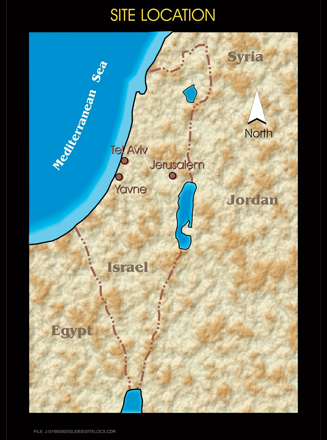
Tel Yavne in Israel is the site of the ancient city of Yavne. Located about 20 kilometers south of Tel Aviv, and about 8 km inland from the ancient seaport of Yavne Yam (meaning Yavne by the Sea), it is believed that underneath the tel (an archaeological mound) are the remains of more than 3,000 years of continuous occupation. The tel, at 4 hectares in area and approximately 30 m in elevation, is relatively large in comparison to other ancient sites in Israel. To date, no excavations have been carried out at the site. In preparation for excavation work at a later date, electrical resistivity tomography (ERT) surveys, ground penetrating radar surveys, and low altitude photography from kites and balloons were carried out at the site. This paper will discuss the ERT and photographic surveys. The objectives of these two surveys were to delineate the plan view and vertical extent of accumulated cultural debris, and to identify particular areas for initial test pitting by archaeologists. Eight ERT cross-sections were imaged, ranging in length from 80 to 140 m. Approximately 500 low altitude photographs were shot. Specific features possibly identified include a 9th century B.C.E. (before the common era) water system, the Philistine city wall dating from 790 B.C.E., the ruins of a 12th century C.E. Crusader castle, and numerous architectural features from the Mameluke, Ottoman, and Palestinian periods of habitation. This is the first time that non- destructive techniques have been used in the first phase of an archaeological exploration program in Israel at such an important, well recognised ancient site.
Introduction
Tel Yavne is a large, ancient tel, located about 20 km south of Tel Aviv (Figure 1). The four hectare tel rises about 30 m above the flood plain of the Soreq River. Potsherds dating to about 1200 B.C.E. have been identified on the surface of the site. Tel Yavne is strategically situated on the Via Maris, the “Way of the Sea,” the ancient highway connecting Egypt and Anatolia by way of Palestine and the Fertile Crescent. The consensus of scholars is that the name of the site has remained unchanged since at least the first millennium B.C.E. (Maeir, 1998). Excavations of the nearby port of Yavne Yam have uncovered remains from as far back as the Middle Bronze age (about 1800 B.C.E.)
Literary references mention Yavne at least as far back as the early first millennium B.C.E. Around 790 B.C.E. the Book of Chronicles describes King Uzziah breaking down the walls of the Philistine city of Jabneh. The city of Yavne appears in references to the Hasmonean wars of the second and first centuries B.C.E., and in references to the Herodian kingdom of the first century B.C.E.
During the first Jewish revolt against the Romans (66 to 70 C.E.), Yavne was captured by the soon to be Roman emperor Vespasian. It is during this time period that a particular event projects Yavne into a prominent position in modern Jewish history and western civilization. In 70 C.E., in the final desperate days of the Roman siege of Jerusalem, Rabbi Yohanan Ben Zakkai was smuggled out of the city in a coffin. Brought to the city of Yavne and the palace of Vespasian, Rabbi Yohanan pleaded for a center of Jewish learning to be established in Yavne to replace that of Jerusalem. Vespasian granted Rabbi Yohanan’s request, and the Yeshiva of Yavne flourished for 60 years. In transplanting Jerusalem as a center of Jewish law and culture, Yavne rescued much of what was Jewish learning up until the destruction of Jerusalem (Neusner, 2003).
Following the Second Jewish Revolt (132 to 135 C.E.), most of the Jewish population areas of southern Israel were destroyed. The Sanhedrin (the Jewish court) was then moved to the Galilee. Yavne thus lost much of its signifcance as a contemporary Jewish center.
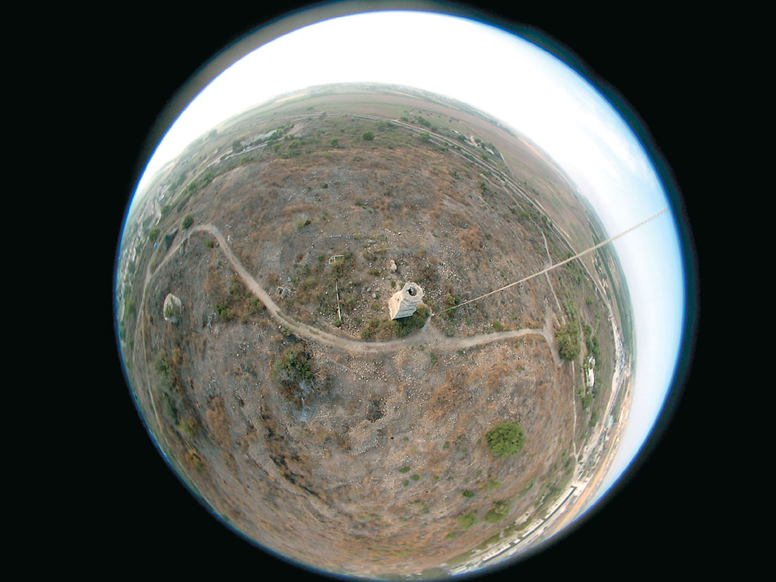
The city continued to exist in the Byzantine period until its capture by the Arabs in the 7th century. The Crusaders captured the city in 1099. In 1141, a large Crusader castle was built as part of a ring of fortresses surrounding the Muslim city of Ashkelon on the Mediterranean coast. In 1244, the Mamelukes captured Yavne and renamed it Yibneh. The most impressive structure still standing on the site today is a Mameluke tower (Figure 2) built adjacent to the Crusader castle walls and incorporated into a mosque (Maeir, 1998). The site continued to exist as an Arab village during the Ottoman period (1516 to 1918) and until 1948, when it was destroyed during the Israel war of Independence.
Despite the close proximity to Tel Aviv and the historical significance of the site, no archaeological excavations have yet been carried out. The overwhelming size of the site has, in itself, been a source of intimidation for many archaeologists interested in the site. The historical significance of the site has been a source of intimidation for developers interested in this large piece of real estate in close proximity to Tel Aviv. Hence, from July 15 to 19 of 2003, geophysical and photographic surveys were carried out at the site in an attempt to delineate the plan view and vertical extent of accumulated cultural debris, and to identify particular areas for initial test pitting by archaeologists.
The tel is underlain by lithified sediments of the Kurkar Group. The Kurkar Group describes coastal sediments from Pliocene through the Recent period that contain considerable amounts of quartz sand grains. These sands are wind blown deposits originating from the Nile delta (Horowitz, 1979). Where present as topographic highs, the Kurkar exists essentially as a lithified sand dune.
Methodology
Electrical Resistivity Tomography
Electrical resistivity tomography (ERT) is a technique used for mapping the distribution of subsurface electrical resistivity in a cross-sectional format. Data are collected through a linear array of 81 stainless steel electrodes coupled to a DC resistivity transmitter and receiver, and an electronic switching box. The switching box directs current from the transmitter to pre-selected pairs of electrodes, and measures voltages from pre-selected pairs of electrodes. The known transmitted current magnitude, the measured voltage, and the active electrode geometry are used to calculate an “apparent” resistivity value for each measurement. The entire data set is then inverted using a two-dimensional (2-D) finite difference, smooth inversion routine. The final product is a 2-D geoelectrical cross-section plotting “true” resistivity (in ohm-m) versus true depth.
The geometry of the four active electrodes (two current and two voltage) used in each measurement have significant relevance in the results of each survey. Different arrays have various advantages and disadvantages. For the surveys carried out at Yavne, data were collected using a Schlumberger configuration. This array geometry dictates that for any four active electrodes, the voltage measuring pair and the current transmitting pair share the same midpoint. The advantages of the Schlumberger array are:
- It provides a relatively large depth of investigation.
- It provides excellent vertical resolution for resolving thin laterally continuous features (such as a floor).
- It provides very good lateral resolution for resolving thin vertical features (such as a wall).
The main disadvantage of the Schlumberger array in contrast to, for instance, the Wenner array, is its lower signal to noise ratio. However, “noisy” data were not a problem given the shallow depths of investigation and the large amounts of current (typically 200 milliamperes) that could easily be injected into the subsurface.
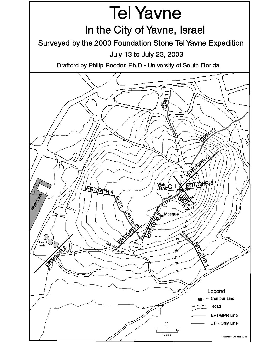
Eight ERT lines were surveyed (Figure 3). They varied in length from 80 m to 140 m. A minimum electrode spacing of 1 m was used for all lines, providing a depth of investigation of 12 m. Each electrode was surveyed for relative elevation along the line using a laser level. The locations of the lines were surveyed with differential GPS. The absolute elevation of the beginning of each ERT line was surveyed with a total station.
Low Altitude, High Resolution Aerial Photography
By the above title, we refer to small format (i.e., large scale or small area) photography from kites or balloons. The photographic techniques from each platform are similar. Kite photography is generally acknowledged to have been invented by Arthur Batut in 1888. By 1890, Batut had published his first book on kite photography – La Photographie aerienne par cerf-volant, or Aerial Photography by Kite. As the airplane had yet to be invented, the technique developed rapidly and was used extensively. In 1906, George Lawrence shot perhaps the first and most famous kite photograph of a population center subject to mass destruction – San Francisco in Ruins. Immediately following the San Francisco earthquake, Lawrence lifted his 29 kg panoramic camera rig with a train of 17 kites connected by piano wire.
Kite photography reached its apex of use during World War I as a reconnaissance and mapping tool in aid of artillery bombardment. Following World War I, the science of aerial photography from aircraft quickly developed and kite photography became a largely forgotten art. Only in the last two decades has the art seen a revival. And only in the last five years has kite photography been recognised as a serious remote sensing tool, even being used to “air truth” satellite photographs for NASA. In fact, the term “kiteography” is now regularly used for the application of kite photography to remote sensing and cartographic tasks. Digital, infrared, stereo, and time lapse photography are all regularly performed from kites. Besides archaeology, applications of kite photography are found in soil science, environmental engineering, geotechnical engineering, hydrology, forestry, agronomy, and even golf course management.
During the photography program at Yavne, both helium filled weather balloons and kites were used as the camera platform. Balloons were used under conditions of wind speeds of less than 8 km/hr. Kites with surface areas of 1.5, 2.8, and 4.6 m2 were employed during conditions of greater wind velocity. Digital, large body 35 mm SLR film cameras, and 35 mm point and shoot film cameras were used. Approximately 500 photographs of Tel Yavne were shot under different lighting conditions and from different altitudes varying from less than about 15 m to approximately 500 m.
Aerial photographs were used for creating base maps, locating ERT lines, identifying surface or near surface archaeological features of interest, and documenting the present conditions of the site.
ERT Lines
Below are described results and interpretations of the eight ERT lines and their inversions. Generally, the ERT geoelectric sections describe a three layer case. Discontinuously present, from surface to a depth of up to 2 m, is a highly resistive layer (greater than 250 ohm-m) imaging structural features (walls, roadways, fortifications, etc.) dating from 1948 back to at least the Crusader period. Most structures in this layer would be built of Kurkar sandstone.
Beneath this upper layer is a conductive second layer of less than 125 ohm-m. This layer ranges in thickness from a few meters to the full thickness of the section, about 12 m. It is believed that this layer represents the cultural debris preceeding the Crusader period and extending back to the Iron or even Bronze age. This layer may consist of weathered, burnt, and collapsed structures originally constructed of mud bricks and some Kurkar sandstone. It is likely that there is considerable infilling with wind blown sediments.
The basal layer varies from being moderately resistive (greater than 125 ohm-m) to highly resistive. This layer is interpreted to be the Kurkar sandstone, likely a lithified sand dune, on top of which habitation was first established.
Some aerial photographs of interest are also noted and described below.
Line 1
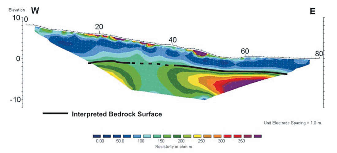
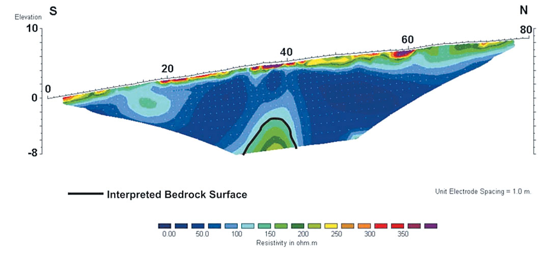
Line 1 is an 80 m section collected in the southeast portion of the tel (Figure 3). The line trends up the slope to the north-northwest. The inverted geoelectric section describes a three layer case (Figure 4). The top layer varies in thickness from 0 to 1.5 m, and the middle layer varies from 3 to 7 m. Clearly, the middle layer thins toward the edge of the mound, and thickens toward the center (the water tank of Figure 3 is located at the top of the mound).
Line 2
Line 2 is a 140 m section collected in the southwest portion of the tel (Figure 3). The line trends up the slope to the northeast. The massive resistive features of the section (Figure 5) are believed to be either fortifications constructed of Kurkar sandstone along the perimeter of the tel, or subcrop of in situ Kurkar sandstone. While it is known that Roman period engineering works (a sewer system) have been uncovered in close proximity to the low elevation flat area of Line 2, it is believed that much of the conductive material imaged in the section is fine grained deposition from the Soreq River flood plain.
Line 3
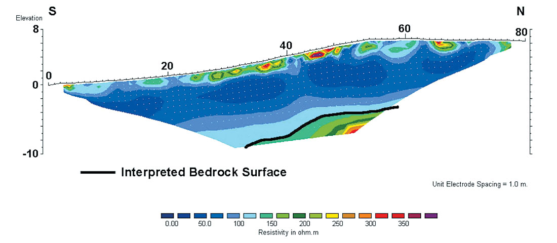
Line 3 is an 80 m line collected more than half way up the slope of the tel (Figure 3). While the top layer of “recent” cultural debris varies from 0.5 to 1.5 m, the interpreted ancient layer occupies almost the entire vertical section with only a small block of Kurkar sandstone poking out of the bottom (Figure 6).
Line 4
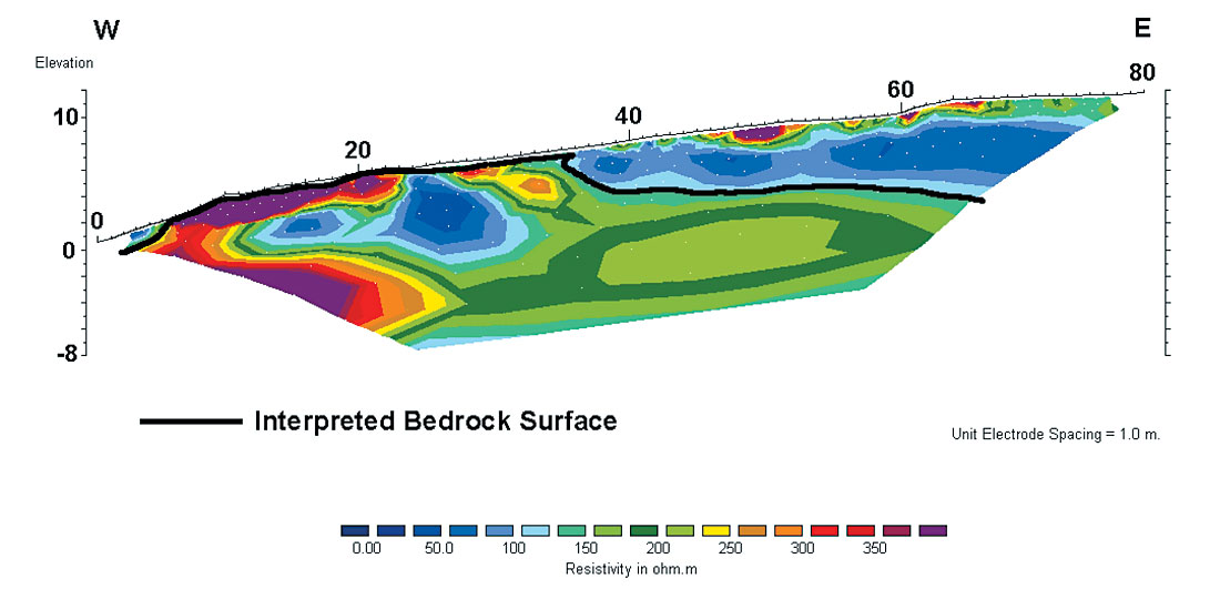
Line 4 is an 80 m line surveyed in a direction trending east from a road at the western perimeter and base of the tel (Figure 3). The road cuts through outcrop of Kurkar sandstone. Kurkar sandstone is exposed on approximately the first third of the line (Figure 7). From the geoelectric section run along this exposure, clearly the Kurkar is resistive. The conductive zone visible inside the Kurkar is due to infill in a clearly visible void. Generally, the Kurkar is soft and easily weathered. Large voids may have been further hollowed out for use as shelters, cisterns, or other storage areas. The thickness of “recent” cultural debris on surface is from 0.5 to 1 m. The thickness of interpreted ancient cultural fill varies from about 3 m thickness at 37 m along the line, to about 7 m thickness at the uphill far end of the line. The cap of cultural fill appears to pinch out around the edges of the tel, and thicken toward the top of the tel.
Line 5
Line 5 is an 80 m section (Figure 3) surveyed near the summit plateau of the tel, on the road passing immediately west of the mosque (Figure 8). The thickness of debris dating from 1948 back to the Crusader period is 1 to 2 m (Figure 9). The middle layer of ancient debris overlying the Kurkar sandstone extends almost the full thickness of the geoelectric section.

Trending almost due north to south, and intersecting the road immediately west of the Mameluke tower, is a series of at least three circular piles of cut rock approximately 10 m across, connected by linear piles of cut rock 10 to 15 m long (Figures 2 and 8). These cut stones are likely the remains of the donjon, or inner keep of the Crusader fortress built by Fulk of Anju in 1141 (Maeir, 1998). The circular piles of stone are likely collapsed battlements. An example of a standing battlement in a Crusader castle contemporary to that of Yavne is seen in the kite photo of the southwest battlement of Belvoir (Figure 10). The double wall construction and standing battlement of the inner keep of Belvoir is seen in the kite photo of Figure 11. The purpose of the double wall was to allow the defenders to retreat to the donjon if the moat and outer wall were breached.
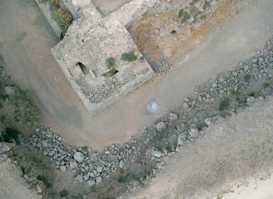
Near the north arrow of Figure 8 are two small, dark shadows about 1.5 m in diameter. These are openings to cisterns of uncertain age. Also visible in the kite photograph are many walls and foundations, most of which likely date from the Ottomon period or later.
Line 6
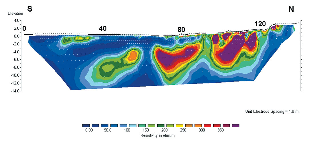
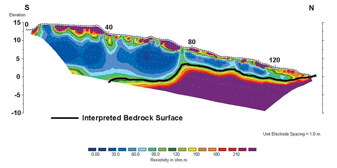
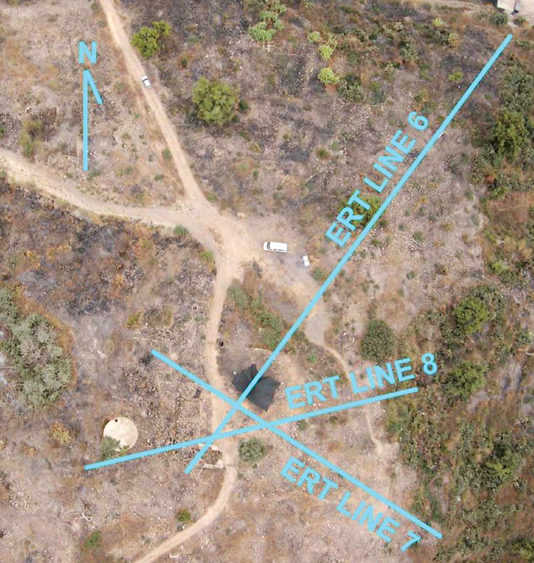
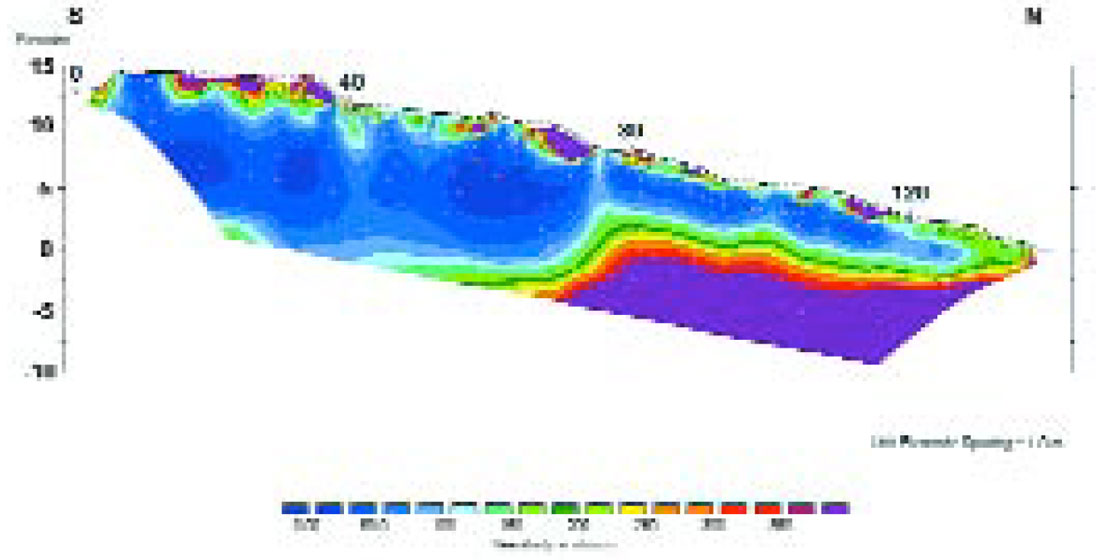
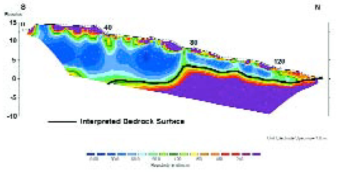
Line 6 is a 140 m northeast to southwest trending section that passes through the highest point of elevation on the tel (Figure 3). Clearly visible at 79 m along the line is a steep cut in the bedrock (Figure 12). It is hypothesized that this is a huge water well similar and contemporary to that constructed in northern Israel in Hazor during the 9th century B.C.E. In ancient times, a reliable and accessible water system was necessary for a city to withstand a siege of any significant period. The opening of the water well in Hazor is 19 X 15 m, and its top was 10 m below the top of the tel. The total depth of the shaft in Hazor is 30 m, 20 m of which was cut through limestone. The upper part of the shaft of Hazor was shored up by huge revetment walls (Yadin, 1975). It is possible that when replotted at a different scale, the vertical features apparent in Line 6 (for instance at 76 m along the line) are also revetment walls (Figure 13).
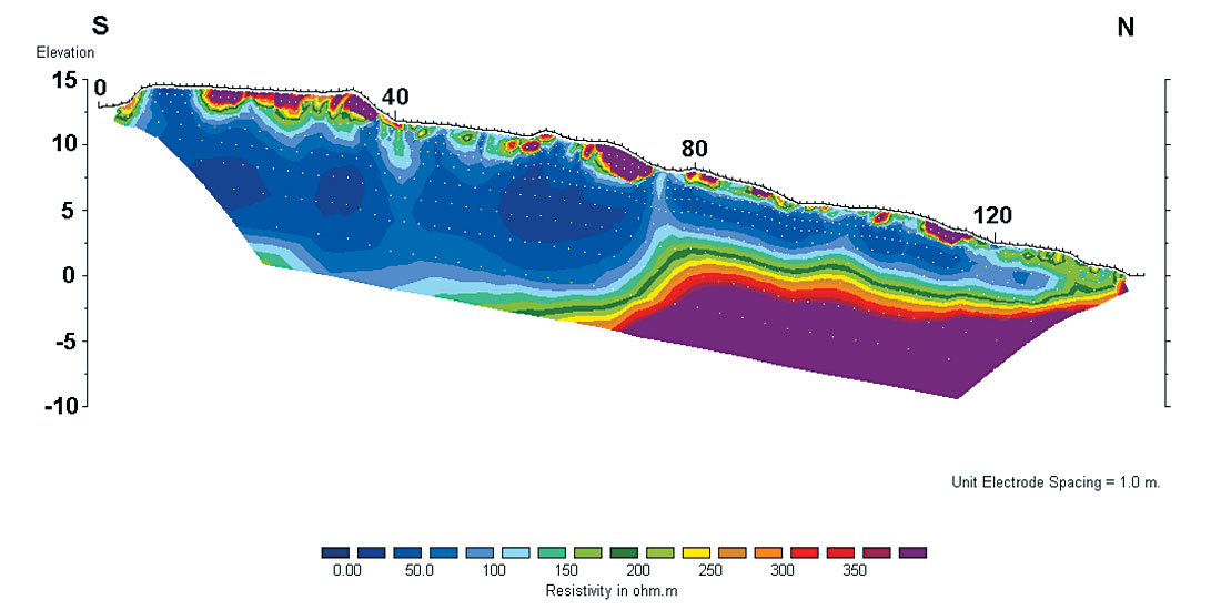
Kite photography also identified a 150 m lineament approximately parallel to and about 80 m east of Line 6. This long, pronounced vegetation lineament is believed to be associated with earth works from the Philistine walled city conquered by Uzziah in 790 B.C.E.
Lines 7 and 8
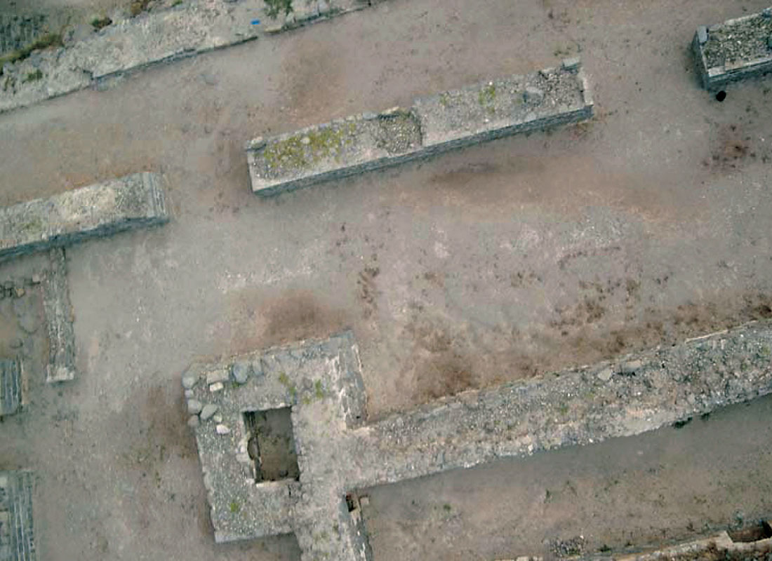
Given the possible significance of the bedrock feature of Line 6, Lines 7 and 8 were run as 80 m long intersecting lines to Line 6 (Figure 3). As seen in the low altitude air photo of Figure 14, Lines 6, 7, and 8 intersect at the point of highest elevation of the mound. Lines 7 and 8 both show 1 to 2 m of recent debris cover. Under this cover, the layer of ancient debris extends to the bottom of the sections (Figures 15 and 16).
Conclusions
It is believed that electrical imaging has been successful at Yavne in identifying the thickness of cultural debris, the plan view extent of cultural debris, and the underlying bedrock contact. The cultural layer varies from a few meters on the edge of the tel to at least 12 m at the top of the tel. The original occupants of the site likely chose it for being situated on a topographic high provided by a Kurkar sandstone outcrop. Specific features of interest to archaeologists were also located. These include the possible water system of the 9th century B.C.E. city, and possible fortifications. The layer of relatively recent building rubble is thin enough to make its removal quite practicable. Additional ERT spreads are planned in order to look deeper in the section, and to give more complete systematic coverage across the site. Archaeological test pitting and physical properties measurements of material in the pits are necessary to confirm the above hypotheses.
Low altitude photography proved very practicable at the site. The inner keep of a 12th century Crusader castle, walls, foundations, cisterns, and other building features of the last millennium were easily identified. The photographs were very functional as base maps for locating the electrical imaging lines. They also serve as a valuable record for documenting the site conditions at the time of the survey. Further photographs are planned under different lighting, vegetation, and moisture conditions at different seasons of the year.


Join the Conversation
Interested in starting, or contributing to a conversation about an article or issue of the RECORDER? Join our CSEG LinkedIn Group.
Share This Article